Manual Power Quality Filter PQFS Electrical design and installation 53
Power Unit 2
Master or Slave Unit
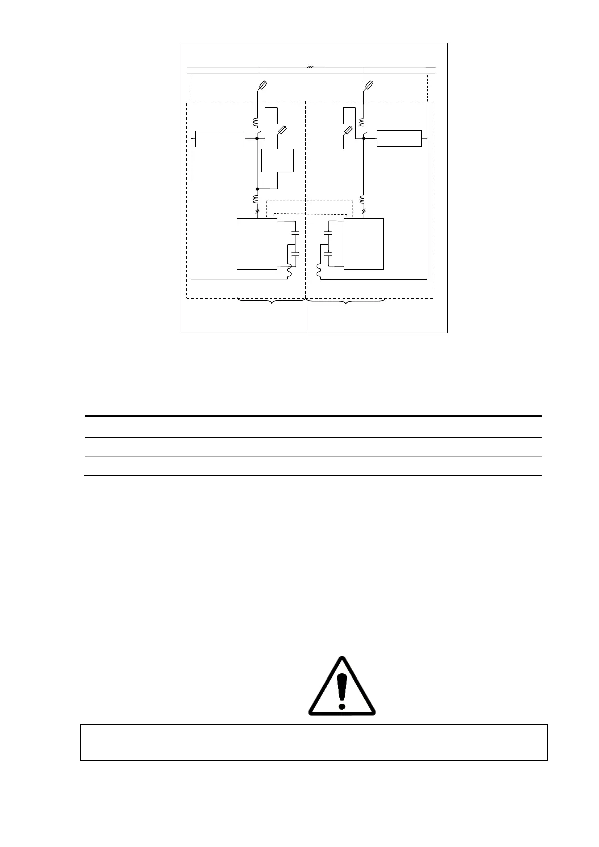
Figure 36: Overview of the connections to be made between two filter enclosures
The interconnection description is given in Table 23.
Table 23: Interconnections between two filter cubicles
1 Control board intercommunication cable through CAN bus (RJ45 cable)
Four steps have to be followed to electrically interconnect a new PQFS unit with an
existing filter. They are outlined in the next four paragraphs.
6.11.1 Mechanical interconnection of the enclosures
All cables to the PQFS unit such as power cable as well as interconnection cable between
modules must pass through the bottom cable entry hole provided in the PQFS box.
6.11.2 Control board cable interconnection
WARNING: Failure to interconnect the control boards in an appropriate way will result
in filter malfunctioning and possibly sever damage of the unit.
Interconnect the control boards of a following unit with a previous filter unit by an RJ45-
based communication cable. This cable is provided with each unit.