Manual Power Quality Filter PQFS Commissioning instructions 91
The filter current spectrum for all phases (3-W mode) and the neutral current spectrum
(4-W mode) in table format for the complete filter system. The table layout is similar to
the one of the voltages (Figure 46) but only absolute current values are shown.
Note: For a multi-unit filter system, the total filter current is an approximate value. More
detailed values for the individual units can be obtained in the ‘Filter currents’-menu.
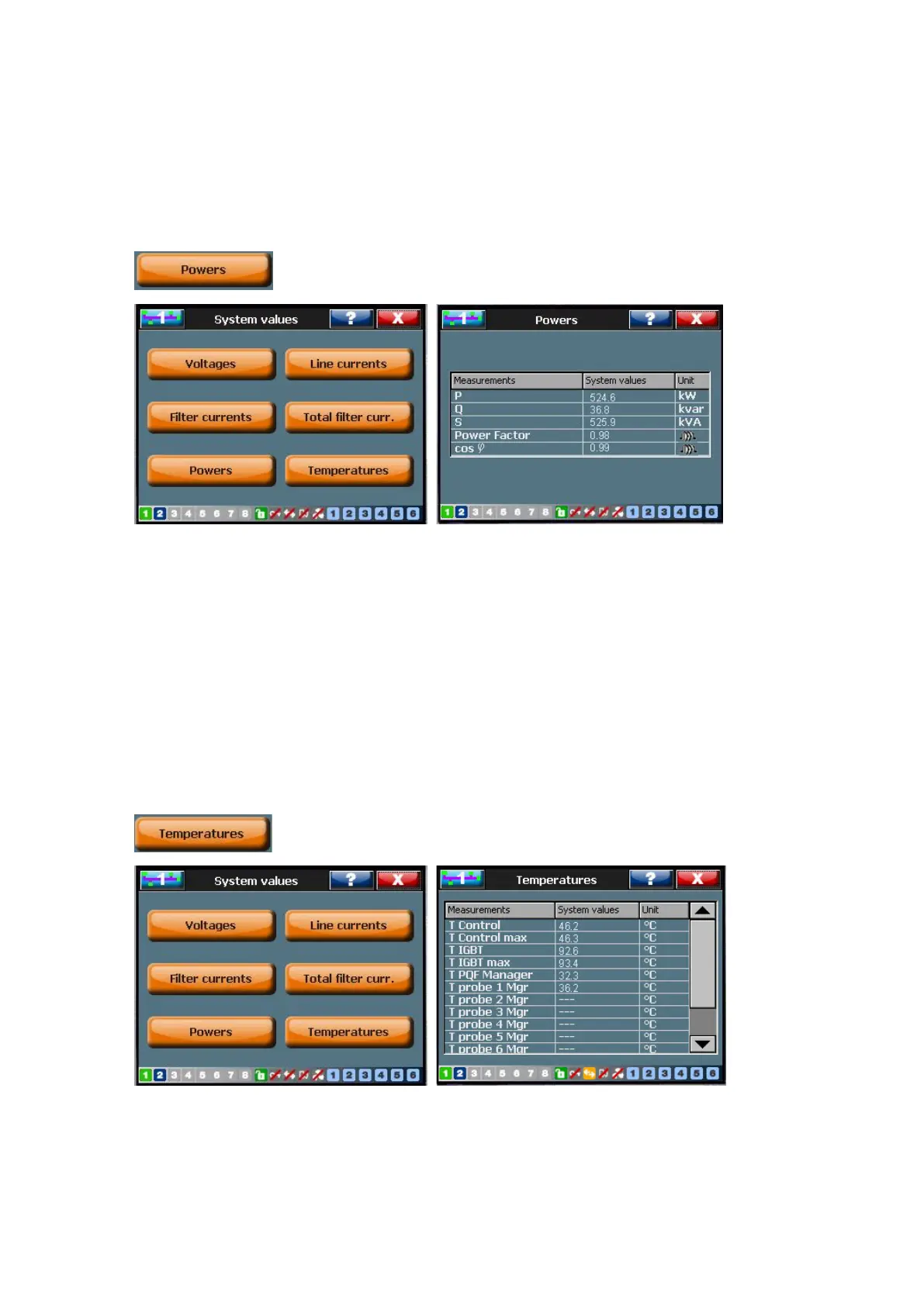
7.8.2.5 Powers
The power in the system at the location of the CTs: (Refer Table 39 for an explanation
of the parameters).
− Active power P
− Reactive power Q
− Apparent power S
− Power factor PF
− Displacement power factor cos ϕ
7.8.2.6 Temperatures
Refer to Table 39 for an explanation of the parameters.
− Temperatures may be expressed in °C and in °F. For changing the temperature
unit, go to [/Welcome/Settings/Customer set. /Temp unit].