Manual Power Quality Filter PQFS Hardware description 25
The PQF-Manager communicates with Modbus TCP and PQ-link thanks to the
Ethernet connection. For background information on the Modbus RTU and TCP
communication interface refer to the dedicated Modbus manual. For background
information on the PQ-link communication interface refer to the dedicated PQ-link
manual.
The PQF-Manager can communicate with PQ-link (PC software) also through USB. .
For background information on the PQ-link communication interface refer to the
dedicated PQ-link manual.
External temperature probes can be added. The PQF-manager can handle until 8
temperature probes connected in a daisy chain way. Please refer to the Temperature
probe User’s guide for more information.
For information on how to cable external systems (e.g. remote control, Modbus
interface) to the PQF-Manager, refer to Chapter 6. For information on how to use the
PQF-Manager, refer to Chapter 7. For background information on the Modbus RTU and
TCP communication interface refer to the dedicated Modbus manual. For background
information on the PQ-link communication interface refer to the dedicated PQ-link
manual.
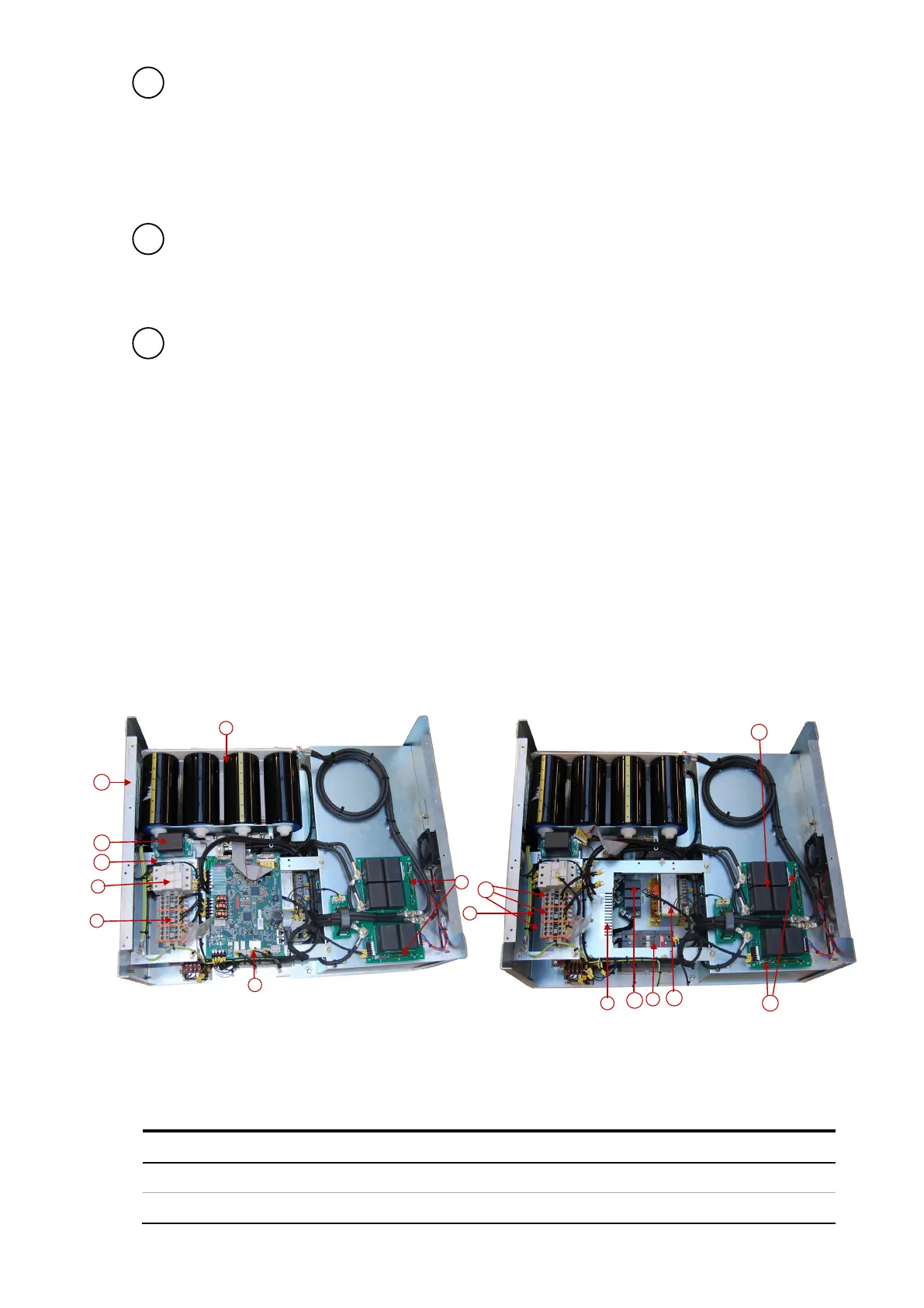
4.6 Location of the main PQFS components
4.6.1 Active filter components
Figure 14 shows a picture of the PQFS without cover panel.
Figure 14: PQFS main components
The component identification is given in Table 11.
Table 11: PQFS main components description
Circuit diagram designation
Main contactor (MC) (underneath controller boards)
Fuse holder auxiliaries circuit