26 Hardware description Manual Power Quality Filter PQFS
3 DC voltage power supply 24V U002
Preload circuit resistors
Main earth connection point
7 IGBT inverter with DC capacitors U01
8 PQF main controller board A005
IGBT heat extraction fans
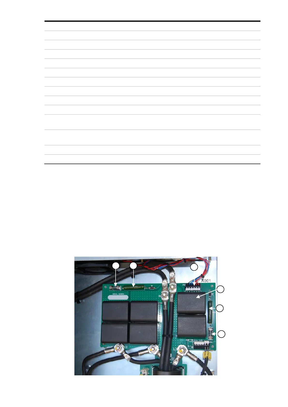
12 PCB output filter preload A001
13 Main power supply terminals (phases) (underneath
controller boards)
L1, L2, L3
14 Main power supply neutral connection (not
mandatory) (underneath controller boards)
N
15 Auxiliary transformer T001
16 Fuse preload circuit PF1, PF2
The PQFS filters are provided with the preload circuit and the output filter mounted on
a PCB. This design substantially reduces the time needed for replacement of the same.
It also gives a more robust design compared to the previous generation of filters. The
power supply to the exhaust fan at the top of the filter are connected to the terminal
block shown which make the replacement of the same easy during periodic
maintenance.
The fuse on the PCB is of very special characteristics and must be replaced only with the
same type. Please refer to our recommended list of spare parts.
The preload circuit is shown in Figure 15.
Figure 15 Preload circuit main components