Manual Power Quality Filter PQFS Hardware description 27
The component identification is given in Table 12.
Table 12: Preload circuit main components description
Circuit diagram designation
Preload circuit resistors
4 Preload circuit resistors R2
5 Capacitors
Terminal block for top fans
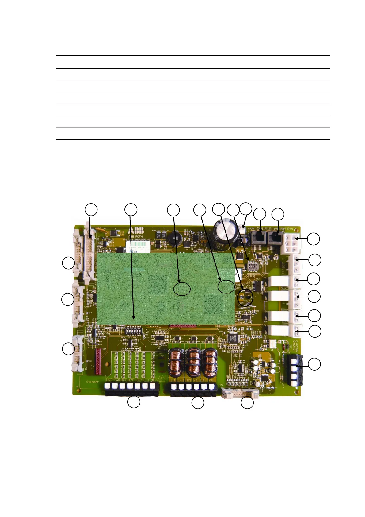
The PQF Main controller board has connectors which are predominantly pre-wired for
use within the filter. However, it also contains a DIP-switch used to set the identification
address and CAN bus connectors for use in a multi-module filter arrangements.
The main controller board is shown in Figure 16.
Figure 16: PQF main controller board
The designation of the principal terminals is given in Table 13.