Manual Power Quality Filter PQFS Hardware description 15
Table 3: User connections for PQFS
2
Power cable connection to the supply (including
neutral connection if 4-wire operation is desired)
Mandatory
Programmable digital outputs (warnings…)
4
Remote control contact connection or/and local
on/off buttons or/and main/auxiliary settings control
Not mandatory
5
PQ-link (USB-Ethernet) – Modbus RTU – Modbus TCP
communication connection
Not mandatory
6
Earth connections from the enclosure to installation
earth
Mandatory
Mandatory connections are connections that must be present to make the filter
operational. Connections that are not mandatory can be made to enhance the filter’s
basic functionality. For more information on cabling the user connections, please refer
to Chapter 6.
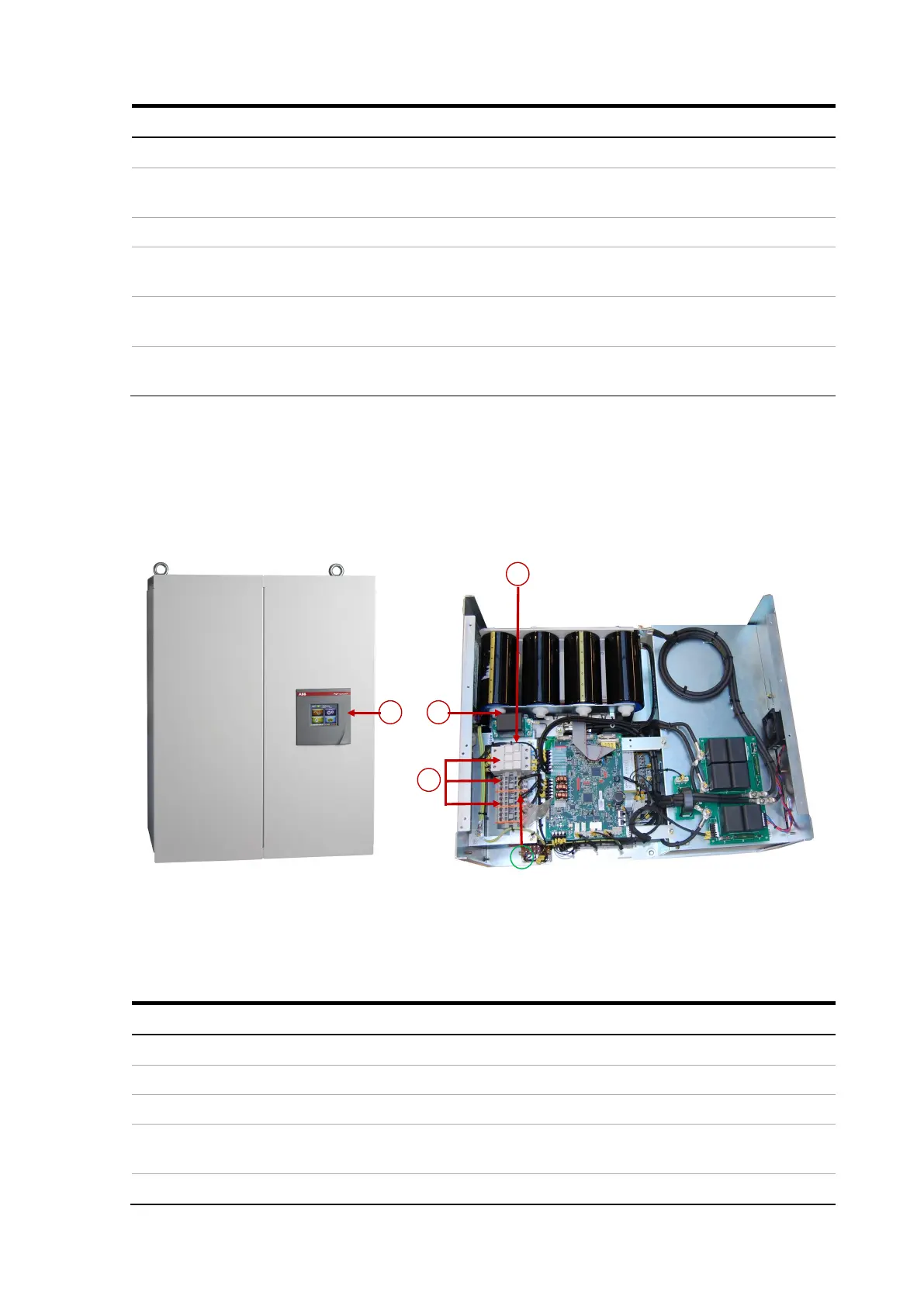
Figure 9 shows a typical PQFS master filter panel.
Figure 9: Example of a typical PQFS master filter panel
The input/output connections and protection description is given in Table 4.
Table 4: Input/Output connections
Item Input/output connections
1 CT connection terminals
2 Main power connection
Auxiliary fuse protection
4
PQF-Manager user interface with connection terminals for user I/O (e.g. alarm
contact) and communication interfaces.