Layout drawing
This section describes the working areas and main components of the MVCS. For more
information, see drawing, 3AES-PVS-100_120_MVCS-30-DW01.
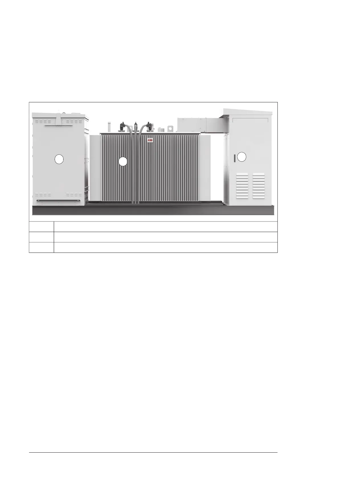
Working areas and main components
40
R0...R2
:
•
•
A
B
C
MV switchgear area. For more information, see section MV switchgear (page 22).
A
MV transformer area. For more information, see section MV transformer (page 23).
B
AC cabinet area. For more information, see section AC cabinet components (page 20).
C
18 Hardware description

 Loading...


