■ String inverter
For information on the inverters, see:
• PVS-100/120-TL Product Manual (9AKK107045A7607)
• String inverter- Product Manual Appendix (9AKK10103A3456)
Main circuit diagram
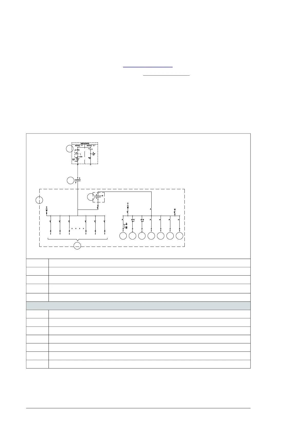
The general single-line diagram depends on the configuration and options of the unit as
well as the configuration of the inverter group. The table below describes the baseline
configuration.
See also, single line diagram 3AES-PVS-100/120_MVCS-01-DW01.
CV MV switchgear (possible to upgrade to CCV)1
MV transformer2
AC cabinet3
Inverter inputs. See also, section Inverter inputs (page 20).
4
Auxiliary service transformer5
Auxiliary service board
AC cabinet heating and fan6
External power socket7
Lighting8
Optional communication cabinet power supply9
MVCS control equipment10
AC cabinet power supply11
Spare12
24 Hardware description

 Loading...


