Operation basics and hardware description 25
Layout drawing
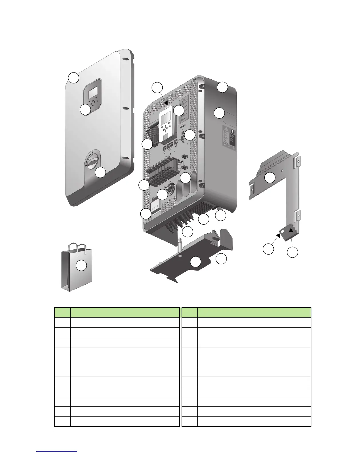
No. Description No. Description
1 Front cover
1)
12 Inlet conduits for control cables, 3 pcs
2 Control area: display, LEDs, keypad 13 Cooling fan and holder
2)
3 DC switch handle 0=Off, 1=On 14 DC connectors
4 Main enclosure 15 AC and PE connection points
5 Type designation label 16 Bottom cover, interlocking
1)
6 Control unit 17 Opening for cabling entrance
7 Stirring fan and holder
2)
18 Installation items
3)
8 Control board terminals 19 Mounting plate
9 String fuses and holders, 8 pcs 20 Point for antitheft padlock
10 DC surge protection device 21 Securing point to inverter
11 DC switch
1)
22 Software versions label
1
2
3
4
5
6
7
8
21
18
12
9
11
10
20
19
17
16
14
13
15
22