Operation basics and hardware description 27
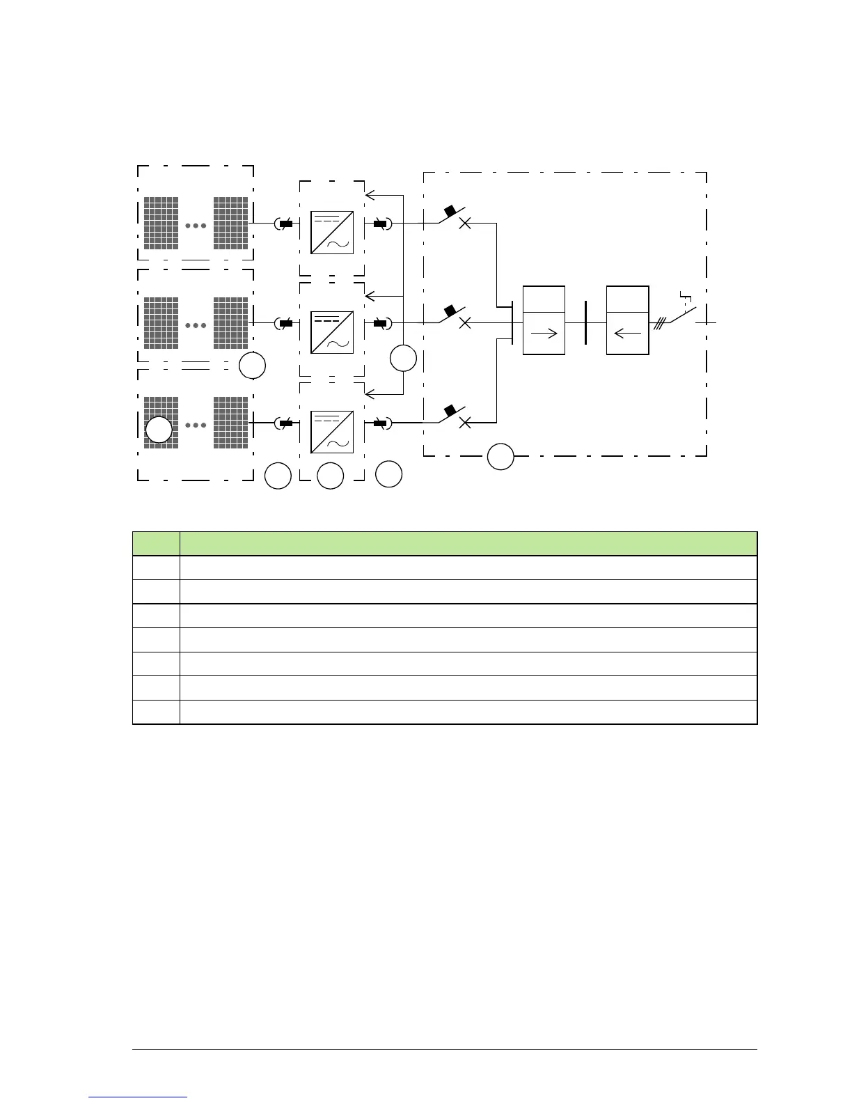
Block diagram of three-phase photovoltaic (PV) system
The figure below shows the three-phase system configuration.
Note: Depending on the local grid code requirements, the circuit breaker at the AC
distribution board can be either a single 3 pole circuit breaker or three identical single
pole circuit breakers.
No. Description
1 Solar module/panel
2 String (array) of solar modules/panels
3 DC input (up to 4 parallel strings)
4 String inverter PVS300
5 AC output, three phases
6 AC distribution board
7 Inverter to inverter communication link (I2I) enabling three-phase grid monitoring
3 ~
kWhkWh
1
2
3
5
6
4
3 x 1/N/PE AC 230 V 50Hz
PV1
PVn
PV1
PVn
PV1
PVn
PVS300
PVS300
PVS300
7