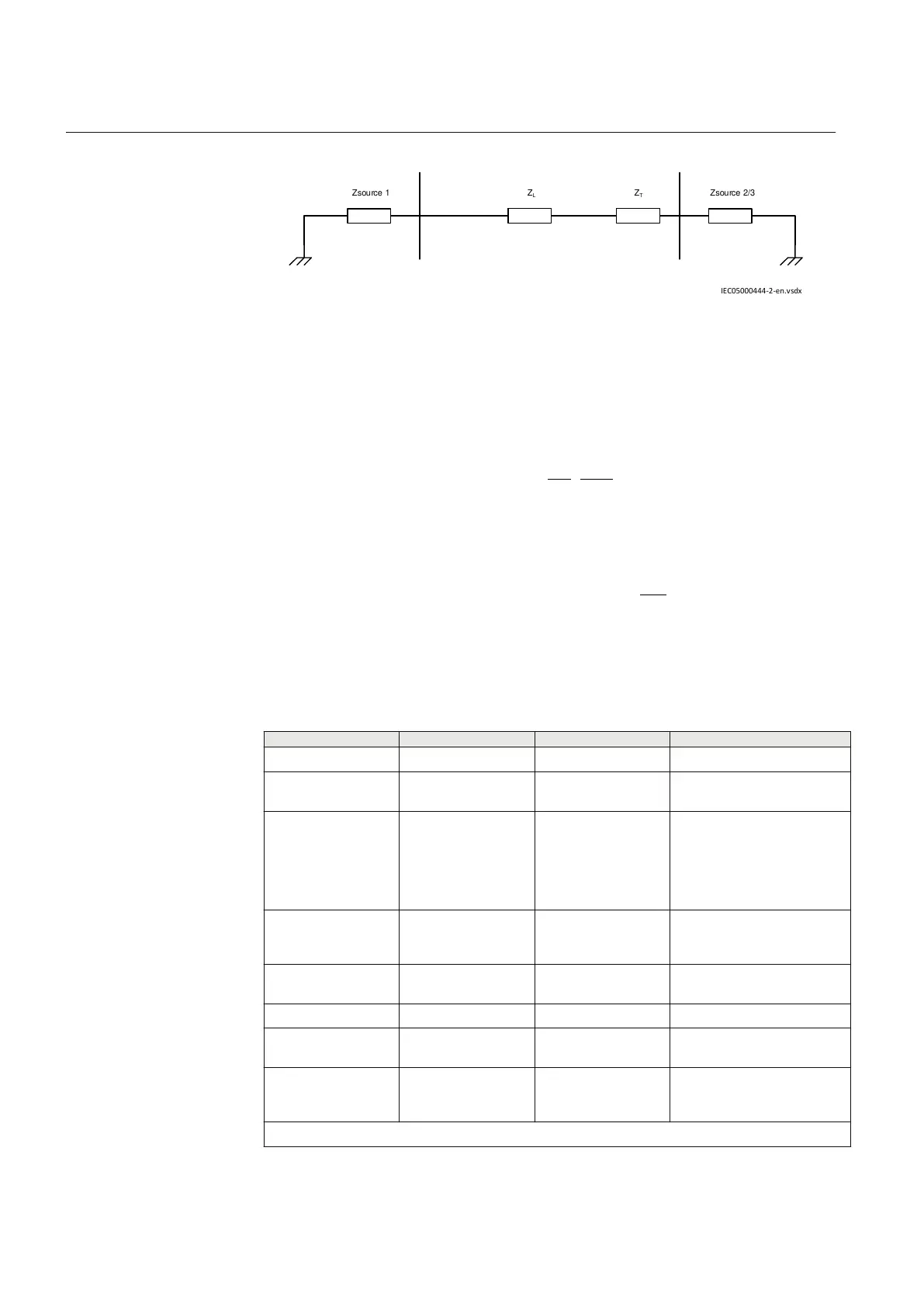
Z
L
Z
T
Zsource 2/3Zsource 1
IEC05000444-2-en.vsdx
IEC05000444 V2 EN-US
Figure 45: Circuit impedances
where:
Line data is
EQUATION1419 V1 EN-US
Transformer data is
2
220
10 220
% 10% 24.2
100 200
T
X X= Þ = × = W
EQUATION1420 V1 EN-US
Source impedance is
EQUATION1421 V1 EN-US
2
Source2 / 3 Source2 / 3 220
220
Z 5 (Z ) 5 49.4
70
= W Þ = × = W
æ ö
ç ÷
è ø
EQUATION1422 V1 EN-US
Table 10: General settings
Setting
IED 1 IED 2 Description
Operation On On Operation Mode (active)
NoOfTerminals 3 3 Number of current sources/
circuit ends
IBase (Global base) 600 A 600 A Reference current of the
protection in the primary
system (note 1)
IBase is set in the Global
base values function
(GBASVAL).
TransfAonInpCh
2 1 Input currents on the input
channels are referred to the
high voltage side (note 2)
TraAWind1Volt
220 kV 220 kV Transformer A: Y-side
voltage
TraAWind2Volt 70 kV 70 kV Transformer A: d-side voltage
ClockNumTransA 1 1 LV d-side lags Y-side by 30
degrees
TransfBonInpCh 3 2 Input currents on the input
channels are referred to the
high voltage side (note 2)
Table continues on next page
Section 6 1MRK 505 393-UEN B
Differential protection
98 Line differential protection RED650 2.2 IEC
Application manual

 Loading...


