4.2.2.4 Examples on how to connect, configure and set CT inputs for most
commonly used CT connections
SEMOD55055-296 v7
Figure
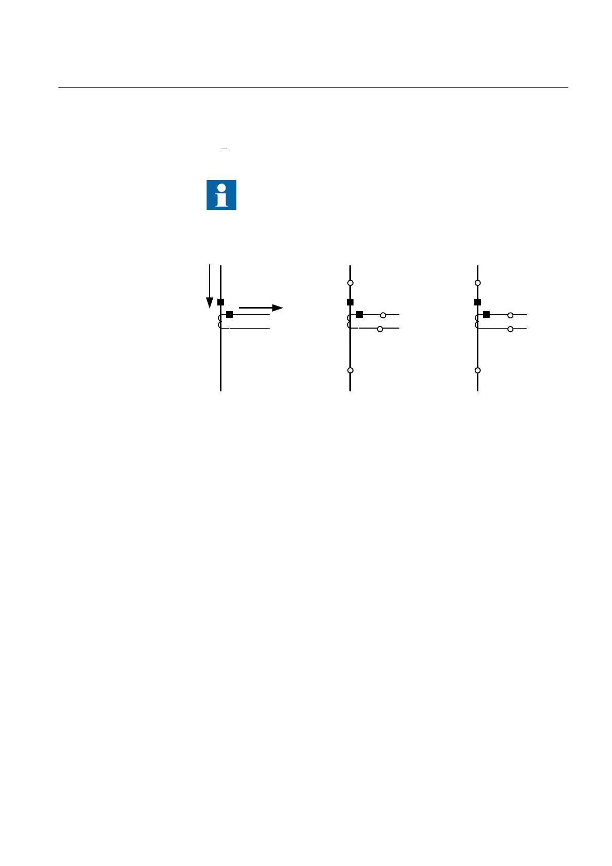
9 defines the marking of current transformer terminals commonly used
around the world:
In the SMAI function block, you have to set if the SMAI block is
measuring current or voltage. This is done with the parameter:
AnalogInputType: Current/Voltage. The ConnectionType: phase -
phase/phase-earth and GlobalBaseSel.
I
Sec
I
P
r
i
S1 (X1)
P1
(H1)
P2
(H2)
S2 (X2)
P2
(H2)
P1
(H1)
x x
a) b) c)
en06000641.vsd
S2 (X2)
S1 (X1)
IEC06000641 V1 EN-US
Figure 9: Commonly used markings of CT terminals
Where:
a) is symbol and terminal marking used in this document. Terminals marked with a square
indicates the primary and secondary winding terminals with the same (that is, positive)
polarity
b) and
c)
are equivalent symbols and terminal marking used by IEC (ANSI) standard for CTs. Note that
for these two cases the CT polarity marking is correct!
It shall be noted that depending on national standard and utility practices, the rated
secondary current of a CT has typically one of the following values:
• 1A
• 5A
However, in some cases, the following rated secondary currents are used as well:
• 2A
• 10A
The IED fully supports all of these rated secondary values.
1MRK 505 393-UEN B Section 4
Analog inputs
Line differential protection RED650 2.2 IEC 45
Application manual

 Loading...


