The minimum primary setting (Is) for the instantaneous phase overcurrent
protection is then:
EQUATION79 V3 EN-US (Equation 96)
The protection function can be used for the specific application only if this setting
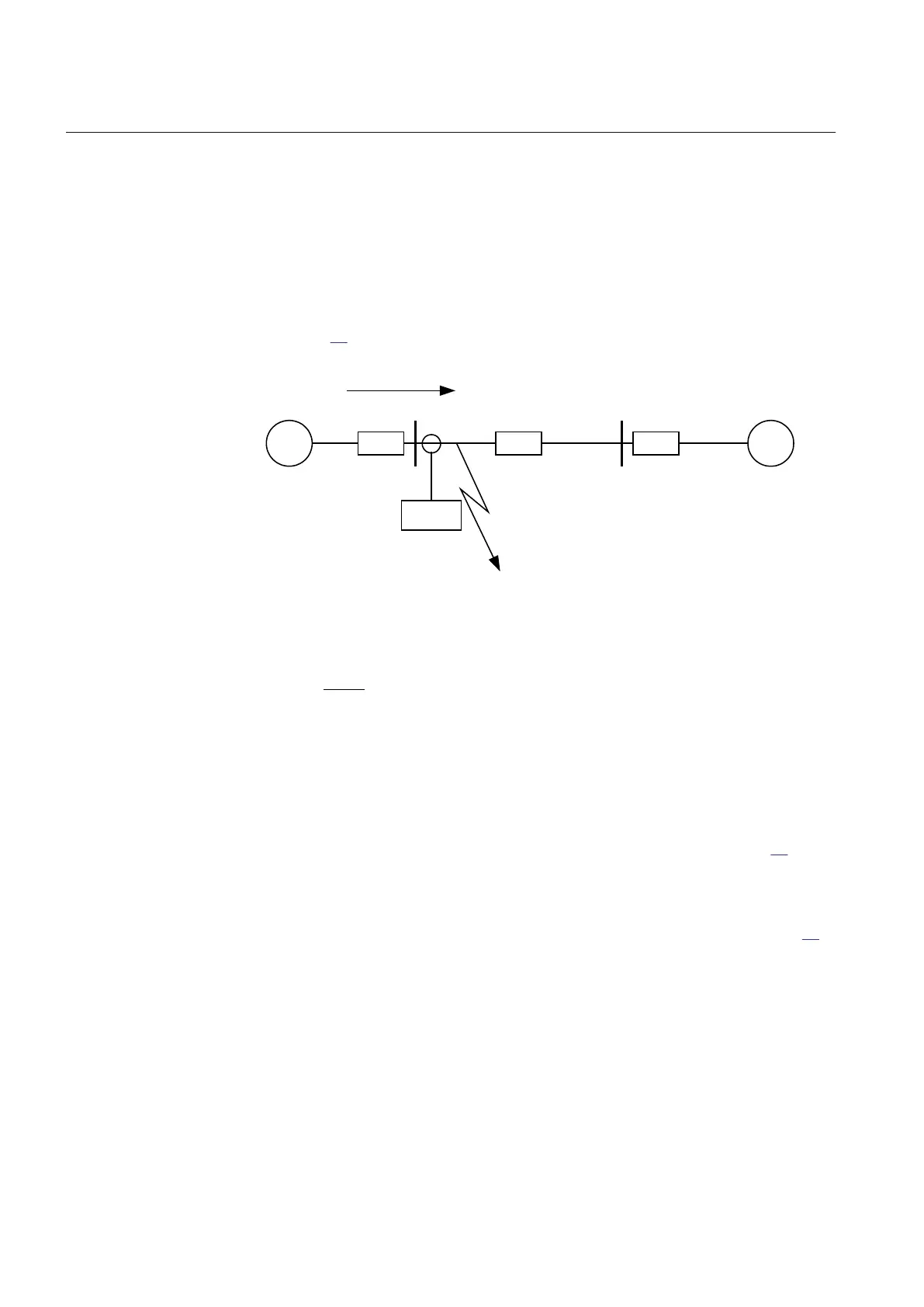
value is equal to or less than the maximum fault current that the IED has to clear, I
F
in Figure 71.
IEC09000024-1-en.vsd
~ ~
Z
A
Z
B
Z
L
A B
IED
I
F
Fault
IEC09000024 V1 EN-US
Figure 71: Fault current: I
F
EQUATION1147 V3 EN-US
(Equation 97)
8.1.3.2 Meshed network with parallel line
M12915-34 v7
In case of parallel lines, the influence of the induced current from the parallel line
to the protected line has to be considered. One example is given in Figure 72,
where the two lines are connected to the same busbars. In this case the influence of
the induced fault current from the faulty line (line 1) to the healthy line (line 2) is
considered together with the two through fault currents I
fA
and I
fB
mentioned
previously. The maximal influence from the parallel line for the IED in Figure 72
will be with a fault at the C point with the C breaker open.
A fault in C has to be applied, and then the maximum current seen from the IED
(I
M
) on the healthy line (this applies for single-phase-to-earth and two-phase-to-
earth faults) is calculated.
Section 8 1MRK 505 393-UEN B
Current protection
150 Line differential protection RED650 2.2 IEC
Application manual

 Loading...


