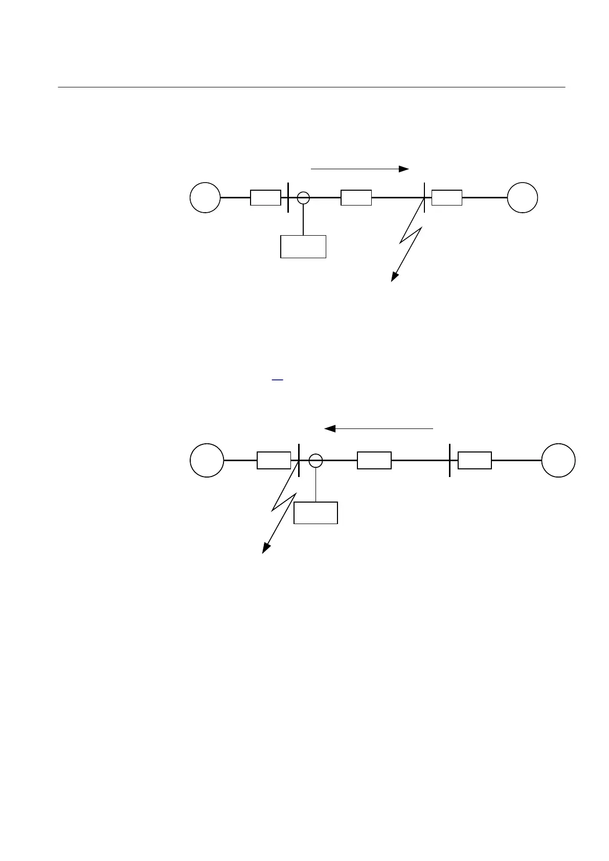
should be done using the minimum source impedance values for Z
A
and the
maximum source impedance values for Z
B
in order to get the maximum through
fault current from A to B.
~
~
Z
A
Z
B
Z
L
A B
IED
I
fB
Fault
IEC09000022-1-en.vsd
IEC09000022 V1 EN-US
Figure 69: Through fault current from A to B: I
fB
Then a fault in A has to be applied and the through fault current I
fA
has to be
calculated, Figure
70. In order to get the maximum through fault current, the
minimum value for Z
B
and the maximum value for Z
A
have to be considered.
IEC09000023-1-en.vsd
~ ~
Z
A
Z
B
Z
L
A B
IED
I
fA
Fault
IEC09000023 V1 EN-US
Figure 70: Through fault current from B to A: I
fA
The IED must not trip for any of the two through-fault currents. Hence the
minimum theoretical current setting (Imin) will be:
EQUATION78 V1 EN-US (Equation 95)
A safety margin of 5% for the maximum protection static inaccuracy and a safety
margin of 5% for the maximum possible transient overreach have to be introduced.
An additional 20% is suggested due to the inaccuracy of the instrument
transformers under transient conditions and inaccuracy in the system data.
1MRK 505 393-UEN B Section 8
Current protection
Line differential protection RED650 2.2 IEC 149
Application manual
 Loading...


