7.1.3.8 Zone reach setting higher than minimum load impedance
GUID-78D0227F-2568-4C9A-8921-45812B4ABAF2 v5
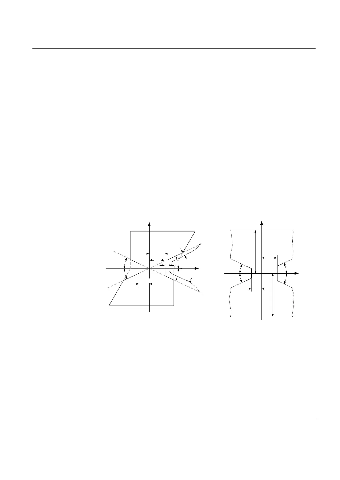
The impedance zones are enabled as soon as the (symmetrical) load impedance
crosses the vertical boundaries defined by RLdFw and RLdRv
[4]
or the lines
defined by ArgLd. So, it is necessary to consider some margin. It is recommended
to set RLdFw and RLdRv to 90% of the per-phase resistance that corresponds to
maximum load.
IECEQUATION2419 V2 EN-US (Equation 73)
IECEQUATION2420 V2 EN-US (Equation 74)
The absolute value of the margin to the closest ArgLd line should be of the same
order, that is, at least 0.1 • Z
load min
.
The load encroachment settings are related to a per-phase load impedance in a
symmetrical star-coupled representation. For symmetrical load or three-phase and
phase-to-phase faults, this corresponds to the per-phase, or positive-sequence,
impedance. For a phase-to-earth fault, it corresponds to the per-loop impedance,
including the earth return impedance.
R
X
RLdFw
RLdRv
ArgLd
90%
10%
10%
ARGLd
Possible
load
ARGLd
ARGLd
R
X
RLdFw
RLdRv
X
L
d
X
L
d
ARGLd
ARGLd
ARGLd
ARGLd
IEC12000176-2-en.vsd
IEC12000176 V2 EN-US
Figure 63: Load impedance limitation with load encroachment
During the initial current change for phase-to-phase and for phase-to-earth faults,
operation may be allowed also when the apparent impedance of the load
encroachment element is located in the load area. This improves the dependability
for fault at the remote end of the line during high load. Although it is not associated
to any standard event, there is one potentially hazardous situation that should be
considered. Should one phase of a parallel circuit open a single pole, even though
there is no fault, and the load current of that phase increase, there is actually no
way of distinguish this from a real fault with similar characteristics. Should this
[4] RLdRv=RLdRvFactor*RLdFw
1MRK 505 393-UEN B Section 7
Impedance protection
Line differential protection RED650 2.2 IEC 129
Application manual

 Loading...


