[ ] = + ×
-
>
æ ö
ç ÷
ç ÷
ç ÷
æ ö
ç ÷
ç ÷
è ø
è ø
p
A
t s B k
i
C
in
EQUATION1189 V1 EN-US (Equation 112)
Further description can be found in the technical reference manual.
tPRCrvx, tTRCrvx, tCRCrvx: Parameters for user programmable of inverse reset
time characteristic curve. Further description can be found in the technical
reference manual.
8.4.3.6 Line application example
M15282-184 v8
Four step residual overcurrent protection can be used in different ways. Below is
described one application possibility to be used in meshed and effectively earthed
systems.
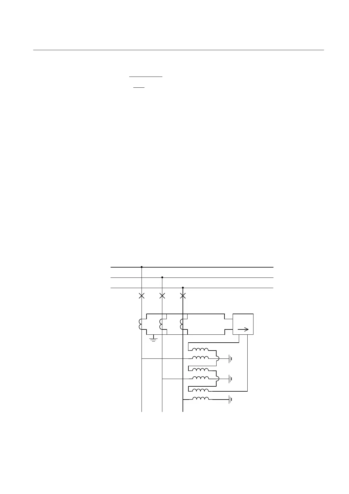
The protection measures the residual current out on the protected line. The
protection function has a directional function where the polarizing voltage (zero-
sequence voltage) is the polarizing quantity.
The polarizing voltage and current can be internally generated when a three-phase
set of voltage transformers and current transformers are used.
IEC05000149 V2 EN-US
Figure 84: Connection of polarizing voltage from an open delta
1MRK 505 393-UEN B Section 8
Current protection
Line differential protection RED650 2.2 IEC 175
Application manual