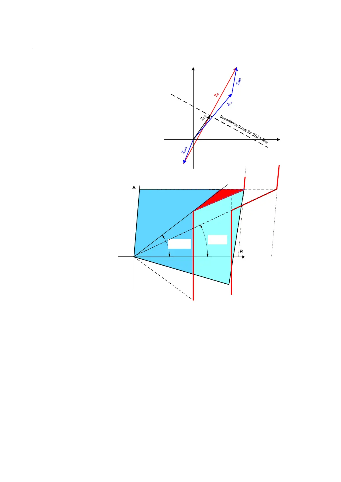
R
jX
ArgLd
(ZMRPSB)
ArgLd
(FDPSPDIS)
jX
R
IEC09000225-2-en.vsdx
IEC09000225 V2 EN-US
Figure 68: Impedance diagrams with corresponding impedances under
consideration
The outer boundary of oscillation detection characteristic in forward direction
RLdOutFw should be set with certain safety margin K
L
compared to the minimum
expected load resistance R
Lmin
. When the exact value of the minimum load
resistance is not known, the following approximations may be considered for lines
with a rated voltage of 400 kV:
• K
L
= 0.9 for lines longer than 150 km
• K
L
= 0.85 for lines between 80 and 150 km
• K
L
= 0.8 for lines shorter than 80 km
1MRK 505 393-UEN B Section 7
Impedance protection
Line differential protection RED650 2.2 IEC 139
Application manual
 Loading...


