When internal voltage selection is needed, the voltage transformer circuit
connections are made according to figure 302. The voltage from the busbar 1 VT is
connected to U3PBB1 and the voltage from busbar 2 is connected to U3PBB2. The
voltage from the line VT is connected to U3PLN1. The positions of the
disconnectors and VT fuses shall be connected as shown in figure
302. The voltage
selection parameter CBConfig is set to Double bus.
15.1.3.4 Double circuit breaker
M12329-3 v7
WA1
WA2
WA1_QA1
WA2_QA1
LINE
WA1_MCB
WA2_
MCB
LINE_MCB
LINE_MCB
WA1_VT
WA1_QA1
GRP_OFF
SESRSYN
U3PBB1*
U3PBB2*
U3PLN1*
U3PLN2*
WA1_VT
LINE_VT
UB1OK
UB1FF
ULN1OK
ULN1FF
WA1_MCB
LINE_MCB
WA2_QA1
GRP_OFF
SESRSYN
U3PBB1*
U3PBB2*
U3PLN1*
U3PLN2*
WA2_VT
LINE_VT
UB1OK
UB1FF
ULN1OK
ULN1FF
WA2_MCB
LINE_MCB
WA2_MCB
WA1_MCB
WA2_VT
LINE_VT
IEC10000096-6-en.vsd
IEC10000096 V4 EN-US
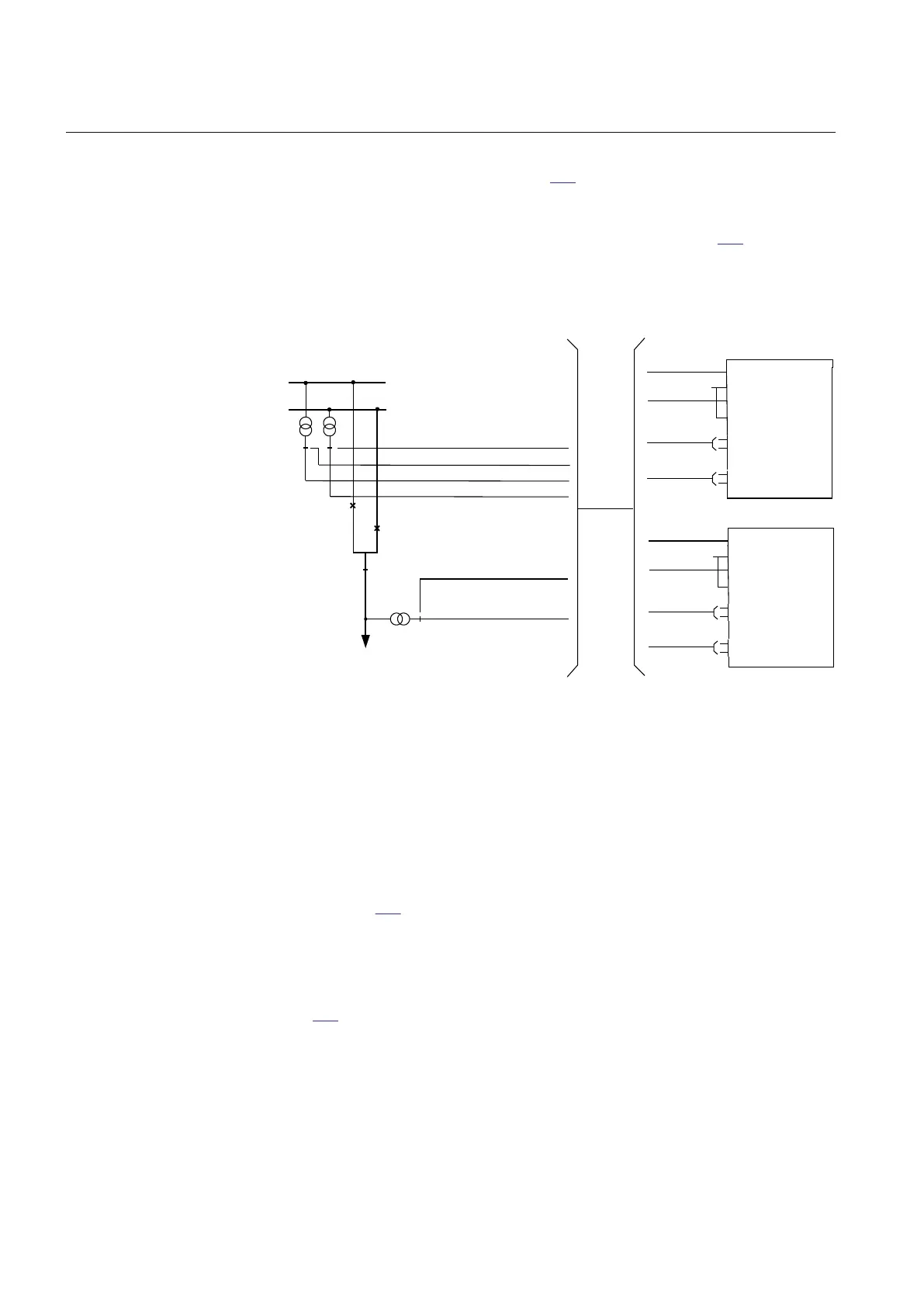
Figure 303: Connections of the SESRSYN function block in a double breaker
arrangement
A double breaker arrangement requires two function blocks, one for breaker
WA1_QA1 and one for breaker WA2_QA1. No voltage selection is necessary,
because the voltage from busbar 1 VT is connected to U3PBB1 on SESRSYN for
WA1_QA1 and the voltage from busbar 2 VT is connected to U3PBB1 on
SESRSYN for WA2_QA1. The voltage from the line VT is connected to U3PLN1
on both function blocks. The condition of VT fuses shall also be connected as
shown in figure
302. The voltage selection parameter CBConfig is set to No voltage
sel. for both function blocks.
15.1.3.5 1 1/2 circuit breaker
M12330-3 v8
Figure 304 describes a 1 ½ breaker arrangement with three SESRSYN functions in
the same IED, each of them handling voltage selection for WA1_QA1, TIE_QA1
and WA2_QA1 breakers respectively. The voltage from busbar 1 VT is connected
to U3PBB1 on all three function blocks and the voltage from busbar 2 VT is
connected to U3PBB2 on all three function blocks. The voltage from line1 VT is
connected to U3PLN1 on all three function blocks and the voltage from line2 VT is
Section 15 1MRK 506 369-UEN B
Control
604 Line distance protection REL670 2.2 IEC
Application manual

 Loading...


