4
.5
.7
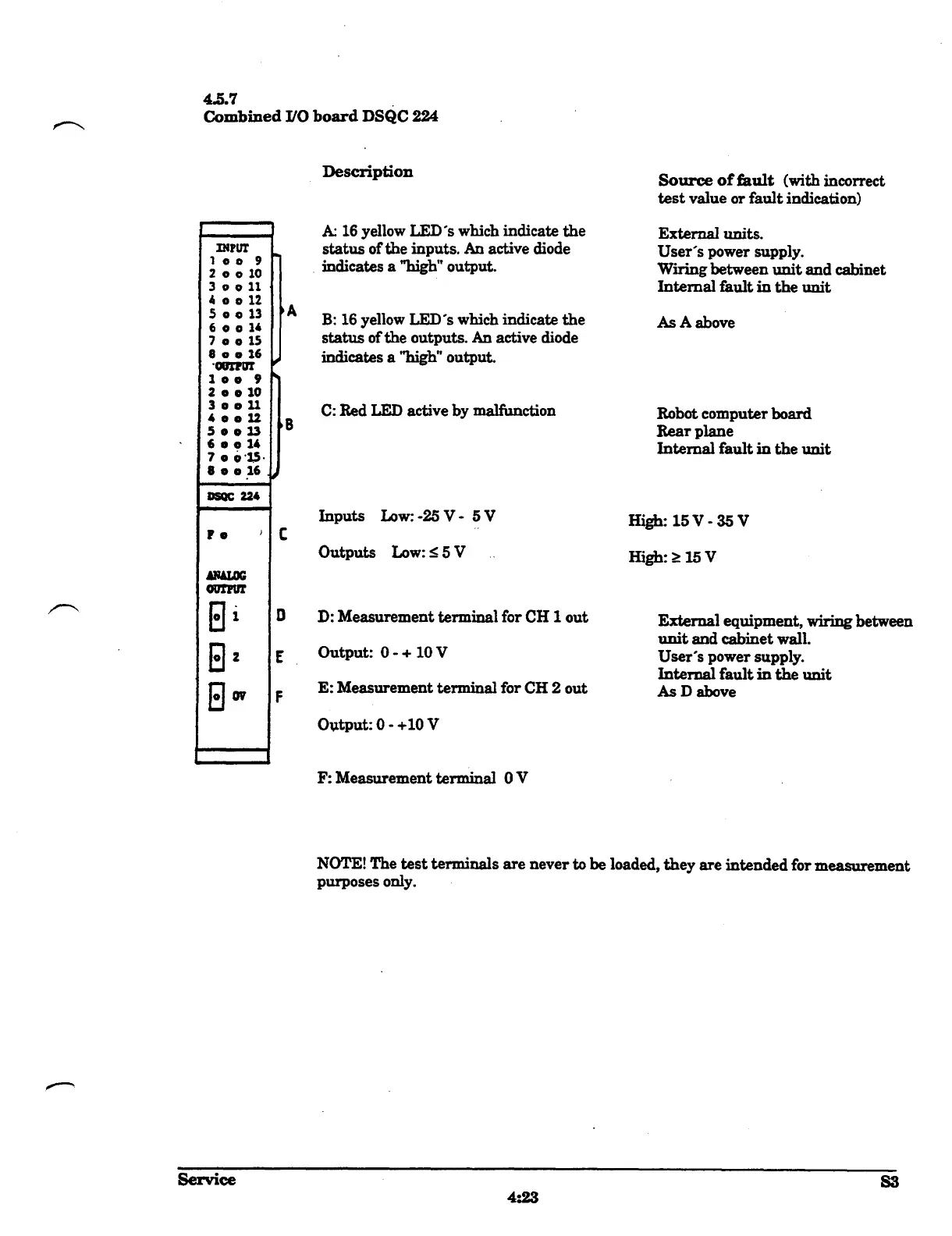
Combined LO board DSQC 224
INPUT
1
0 0
9
2 o
0
10
30011
4a012
5aa13
6 a a 14
70015
8
0
a 16
.
10111
=
loo 9
2 e o10
3o011
40012
50013
6
0
o 14
700'1,5
•
•
~
0016
OW 224
•
~
0
OUTPUT
I
1
2
0v
i
Service
C
D
F
A
B
Description
A 16 yellow LED's which indicate the
status of the inputs . An active diode
indicates a "high" output
.
B
: 16 yellow LED's which indicate the
status of the outputs . An active diode
indicates a "high" output
.
C
: Red LED active by malfunction
Inputs Low
: -25 V -
5 V
Outputs Low
: <_ 5 V
D
: Measurement terminal for CH 1 out
Output
: 0
-
+ 10 V
E
: Measurement terminal for CH 2 out
Output
: 0 -
+10 V
F
: Measurement terminal 0
V
4
:
2
3
Source of fault
(with incorrect
test value or fault indication)
External units
.
User's power supply
.
Wiring between unit and cabinet
Internal fault in the unit
As A above
Robot computer board
Rear plane
Internal fault
in the unit
High
: 15 V
-
35 V
High
: _ 15 V
External equipment, wiring between
unit and cabinet wall
.
User's power supply
.
Internal fault in the unit
As D above
NOTE! The test terminals are never to be loaded, they are intended for measurement
purposes only
.
I
S3