152 System Manual SCK Gas Sampling System 42/23-81 EN Rev. 4
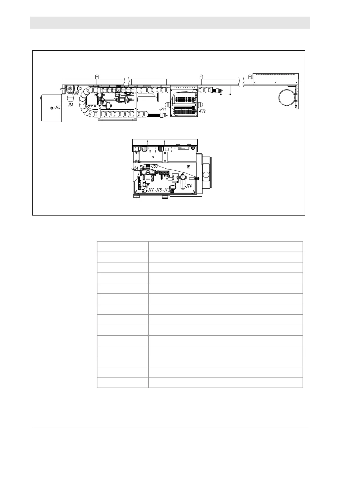
Equipment layout plan
Diagram of the location of maintenance-relevant equipment on the retractor (de-
tailed view of pneumatic box below):
The following table lists the above-mentioned equipment:
Equipment ID Designation
-J53
Filter/pressure control combination
-J54
Compressed-air gate valve
-J74
Pneumatic motor oiler
-J75
EMERGENCY-STOP switch for probe movement
-J77
Pneumatic valve "Insert probe"
-J78
Pneumatic valve "Retract probe"
-J79
Pneumatic valve "shutter"
-J81
Pneumatic motor
-J82
Gate valve
-J83
Air filter
-P71
Probe movement warning lamp
-P72
Probe movement warning lamp
not illustrated
Position indicators -B71, -B72, -S72
Illustration
Equipment