42/23-81 EN Rev. 4 System Manual SCK Gas Sampling System 47
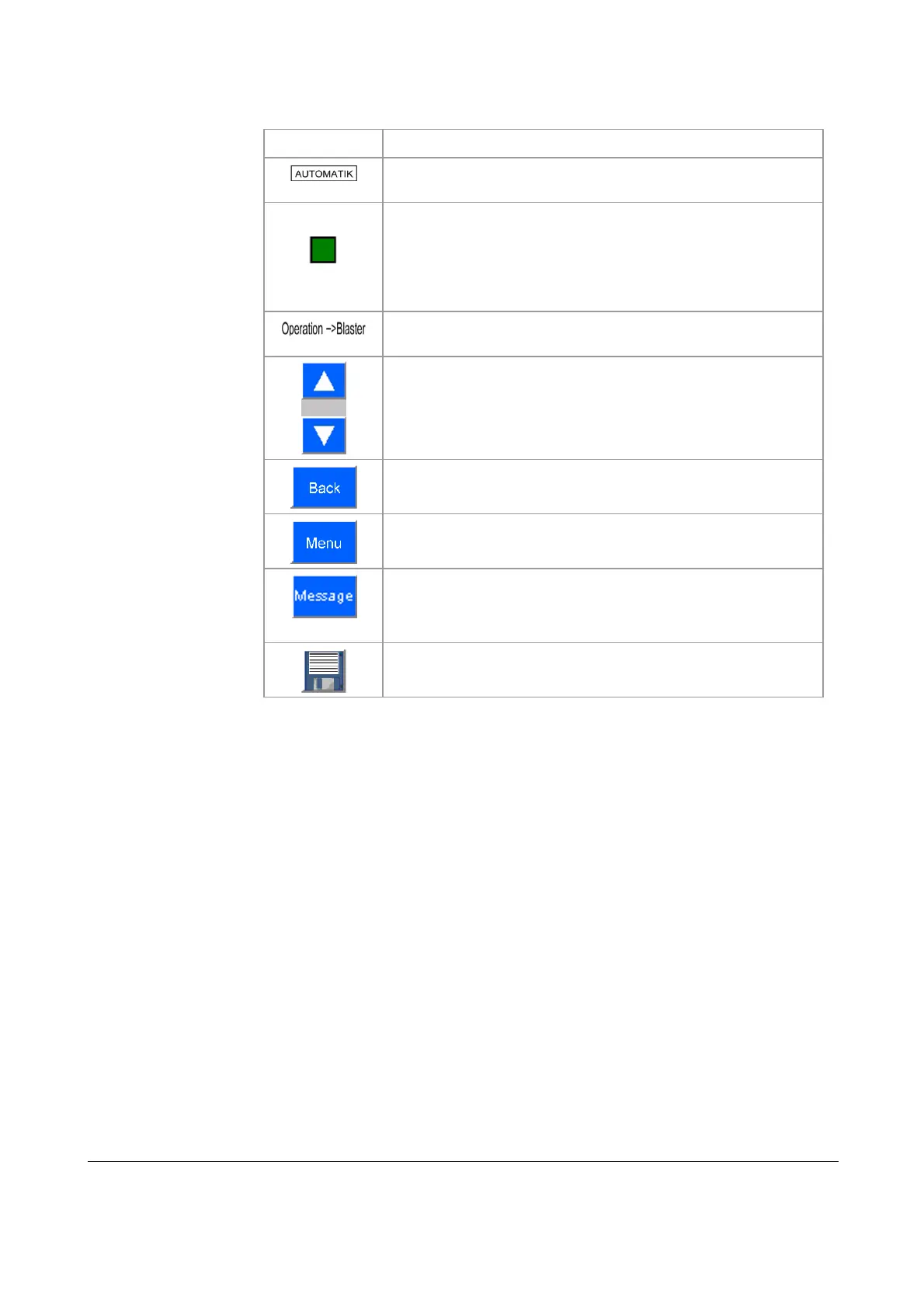
The following table lists the buttons and displays in the user interface and their
functions:
Symbol Function
Displays the mode (AUTOMATIC or MANUAL)
System status lights:
green: normal operation
red: error
orange: maintenance required
blue: maintenance
Menu path display
Scroll up or down in the parameter list
Jump to previous menu
Jump to main menu
Display Message menu
Save contents: save parameter settings
The control system has factory settings that need to be modified to specific system
conditions at start-up. You can edit alarm limits in a set range to suit specific sys-
tem conditions. Touch a parameter entry to select it. The program displays an input
box for you to input the appropriate value.
Buttons and symbols
Edit parameters