96 System Manual SCK Gas Sampling System 42/23-81 EN Rev. 4
Step Procedure
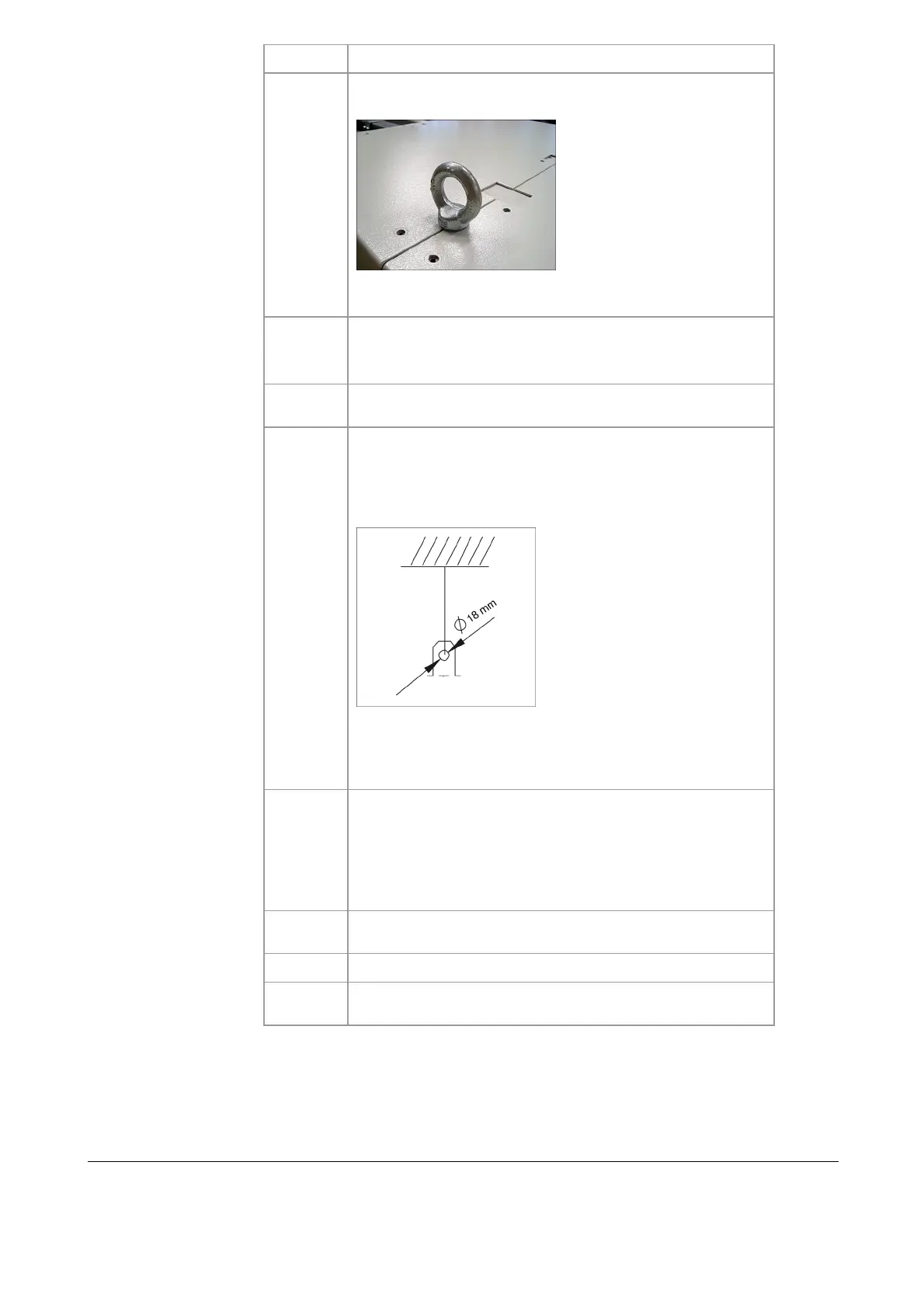
2
Suspend probe retractor on transport lugs (see photo) using
suitable lifting gear.
Note: Pay particular attention to suitable fastening points of
the lifting equipment. Observe relevant local regulations.
3
Lift probe retractor so far that you can remove the two
mounted transport supports.
Note: Store the transport supports for any future transport.
4
Position probe retractor in the designated position and install
appropriate support.
5
Connect the fastening elements of the probe retractor and
the system. There are 6 fastening straps on the probe re-
tractor for this purpose (see Figure). Maximum load per
suspension point is 10,000 N; ensure even loading of the
fastening elements.
CAUTION! The screw-in transport lugs are for transporting
the probe retractor only but not for permanent suspension.
For permanent suspension of the probe retractor, only
use the 6 designated fastening straps.
6
Remove dummy flange on wall tube.
WARNING! Risk of burning due to jet flames and hot gases
at the uncovered duct opening when the rotary kiln is in
operation. Wear a face mask against heat, heat-proof
gloves and protective welder's clothing and respiratory
protection against toxic gases.
7
Flange the mounting flange of the probe retractor on the kiln
wall tube.
8
Remove lifting gear and support material.
9
Check whether probe retractor is fastened stably enough
and adjusted to local conditions.
During assembly it may be necessary to move the probe retractor without with
compressed-air supply or control cabinet. However, this should be limited to abso-
lutely necessary cases. Proceed as follows:
Moving the probe
during assembly
 Loading...


