Connecting terminals
for PTC sensors
Current path
(for measuring
the motor current)
Connecting terminals
for the digital inputs
Connection
for the
Control
Panel
Communication
interface for PROFI-
BUS. Alternatively ad-
apters for Modbus
RTU and DeviceNet
are available.
Front label,
e.g. for slave
address
24 V DC, GND
Supply voltage
Connecting terminals
for communication with
the expansion modules
After powering on, the UMC100.3 performs a self-test of its hardware and checks the configuration for consistency.
In the event of a failure, a self-test fault is generated and signalled. Replace the device in such a case.
After a successful self-test the UMC enters the operational state.
For the 24 V DC power supply, always use an SELV or PELV power supply unit!
Description of Components
UMC100.3
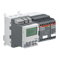
The following diagram shows the terminals, monitoring and operating elements of the UMC100.3. The UMC is shown with PDP32.0
as an example for a communication interface.
110-240 V AC/DC
supply voltage
24V DC, GND for
supply of expansion
modules
Output relay
(Common root and
contactors)

 Loading...