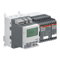
Use the LCD panel as automatic parameter backup storage
All settings can also be stored in the operator panel automatically. This is interesting in case of a UMC100.3 replacement. This new
function requires that UMC and operator panel have revision.
• UMC100.3 SW: 3.07 check via operator panel Maintenance/service -> UMC100 SW version
• Operator panel SW: 4.0
This function is not supported in the UMC100.3 ATEX and UMC100.3 ATEX with conformal coating!
The function stores
• All UMC100.3 parameters for configuration
• Custom application
• Fieldbus address
• Address check
• I/O Data profile
• DeviceNet communication baudrate
• MODBUS communication data (baudrate, frame format, timeout)
• Retrofit
• Parameter for Ethernet/IP
It does not store
• Counter values (Number of trips, thermal trips, starts, emergency starts, operating hours, stand still hours, energy)
• All data related to the thermal memory (motor model)
• Historical data from function block NON_VOL_SR_FF
This function is by default deactivated (Auto Save = OFF).
Activation of auto save function
After configuration of the UMC100.3 the auto save function must be enabled. The activation is done by setting the parameter “Ena-
ble Auto Save = ON” in the LCD panel menu.
• All settings as mentioned above are now uploaded to the operator panel, the green LED on the UMC100.3 is flashing. This
transfer takes a few minutes (~ 3 min.). After successful writing a disk symbol on the LCD-Panel indicates that this function is
activated.
• From now on changed parameters are continuously stored into the LCD-Panel. Writing is indicated by the flashing disk symbol.
• At the next UMC100.3 startup a LCD-Panel with saved parameters is expected.
Deactivation of auto save function
With an activated parameter “Enable Auto Save = ON” the UMC100.3 always expects a valid LCD panel at startup. To deactivate this
function:
• Set the parameter “Enable Auto Save = OFF” with the LCD-Panel
• The parameters stored in the LCD-Panel are deleted.
• During the next startup the UMC100.3 use the internal stored parameters.
UMC100.3: The green LED is blinking during the data transfer from LCD panel into UMC100.3.
LCD-Panel: In the main menu, in the Status line (first line) the text message “Download to UMC” is blinking. When the download to
UMC100.3 is finished the normal text is displayed and a disk symbol is activated in the first line on the left side.
Replacing operator panel UMC100-PAN
UMC100.3: The green LED is blinking during the data transfer to the LCD-Panel.
LCD-Panel: In the main menu, in the Status line (first line) the text message “Upload to LCD panel” is blinking. When the upload to
LCD-Panel is finished the normal text is displayed and a disk symbol is activated in the first line on the left site.
Parameter setting for warning “LCD panel missing”
A warning “LCD panel missing” can be enabled or disabled. The parameter is located in menu Display -> En Auto Save React. The de-
fault value is ON. If the function “Enable Auto Save” is activated and the LCD-Panel is disconnected later, a warning is generated
“LCD panel missing”. This warning is also sent via fieldbus/network in the Diagnosis Byte 4 Bit 0.
Do not remove the LCD panel or power off the UMC100.3 in following cases
• The text message “Upload to LCD panel” is blinking
• The text message “Download to UMC” is blinking
• The disk symbol is blinking.
110

 Loading...