Do you have a question about the ABB UMC22-FBP and is the answer not in the manual?
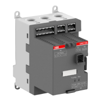
Identifies and explains the function of all connection terminals, indicator LEDs, and front panel controls.
Describes the detection and handling of earth faults using the CEM11 sensor.
Explains how to utilize PTC sensors for enhanced motor temperature monitoring and protection.
Details the data structures for monitoring, commanding, and diagnosing the device via bus communication.
Explains the PTC protection features and their technical specifications.
Describes the basic I/O operation mode where inputs/outputs are directly connected to the fieldbus.
Details the configuration for using the UMC22 as a standalone overload relay for motor protection.
Explains the setup and operation for a basic motor starter controlling one direction of rotation.
Covers the configuration for controlling motors in both forward and reverse directions.
Details the implementation of a star-delta starter for reduced starting current.
Explains an alternative star-delta starting configuration with specific differences from starter 1.
Describes the control for two-pole or Dahlander motors allowing speed changes.
| ABB Type Designation | UMC22-FBP |
|---|---|
| Rated Control Supply Voltage (Us) | 24 V DC |
| Protection class | IP20 |
| Input Current | 0.5 A |
| Output Current | 0.5 A |
| Communication | Modbus RTU |
| Display | No |
| Operating temperature range | -25 °C to +55 °C |
| Storage temperature range | -40 °C to +70 °C |
| Relative humidity | 5 ... 95 % |
| Communication interface | PROFIBUS DP, DeviceNet, CANopen, Modbus RTU, Ethernet/IP, PROFINET |
| Protocol | PROFIBUS DP, DeviceNet, CANopen, Modbus RTU, Ethernet/IP, PROFINET |