- 12 -
18 17 16 15 14 13 12 1 1 10
DI DI DI DI DI DI 24 24 0
5 4 3 2 1 0 V V V
EXT .
T1
8
DO
1
7
DO
0
6
DO
C
5
DO
C
9
DO
2
8 7 6 5 9 T2 3 4
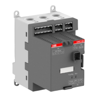
UMC22
READY
MOT .ON
F AUL T
LOC
2CDC 342 008 F0007
UMC22-FBP
Universal Motor Controller UMC22-FBP
Software version 4.0
FieldBusPlug / Issue: 02.2008
V 6
Connecting terminals for PTC sensors
Current path (for measuring the motor current)
Mounting by 4 screws M4
Connecting terminals for the digital outputs
Pawl to snap up the Control Panel
:
Plug connection for the Control Panel
LEDs:
green READY (for operation)
yellow MOT.ON (motor on)
red FAULT (overload, failure)
Connector for the FieldBusPlug
DIN rail
Front label, e.g. for slave address
Control Panel holder. Insert the Control Panel at
this holder then snap it into the pawl on the upper
side. The electrical contacts are automatically
connected.
Connecting terminals for the digital inputs
Connecting terminals for the external supply
voltage (supply for internal electronics)
Current path (for measuring the motor current)
Snap-mountable Control Panel ACS100-PAN for
monitoring and control / adjust:
- slave address
- control function
- overload parameters
- on-site diagnosis
- etc.
The Control Panel ACS100-PAN is not shipped
together with the UMC22-FBP. It must be ordered
separately.
Fig. 2-3: Terminals, monitoring and operating elements of the UMC22-FBP
Dimensions see chapter 5.7.
Chapter 2.2~1
2.2 Terminals, monitoring LEDs and operating elements on the front plate