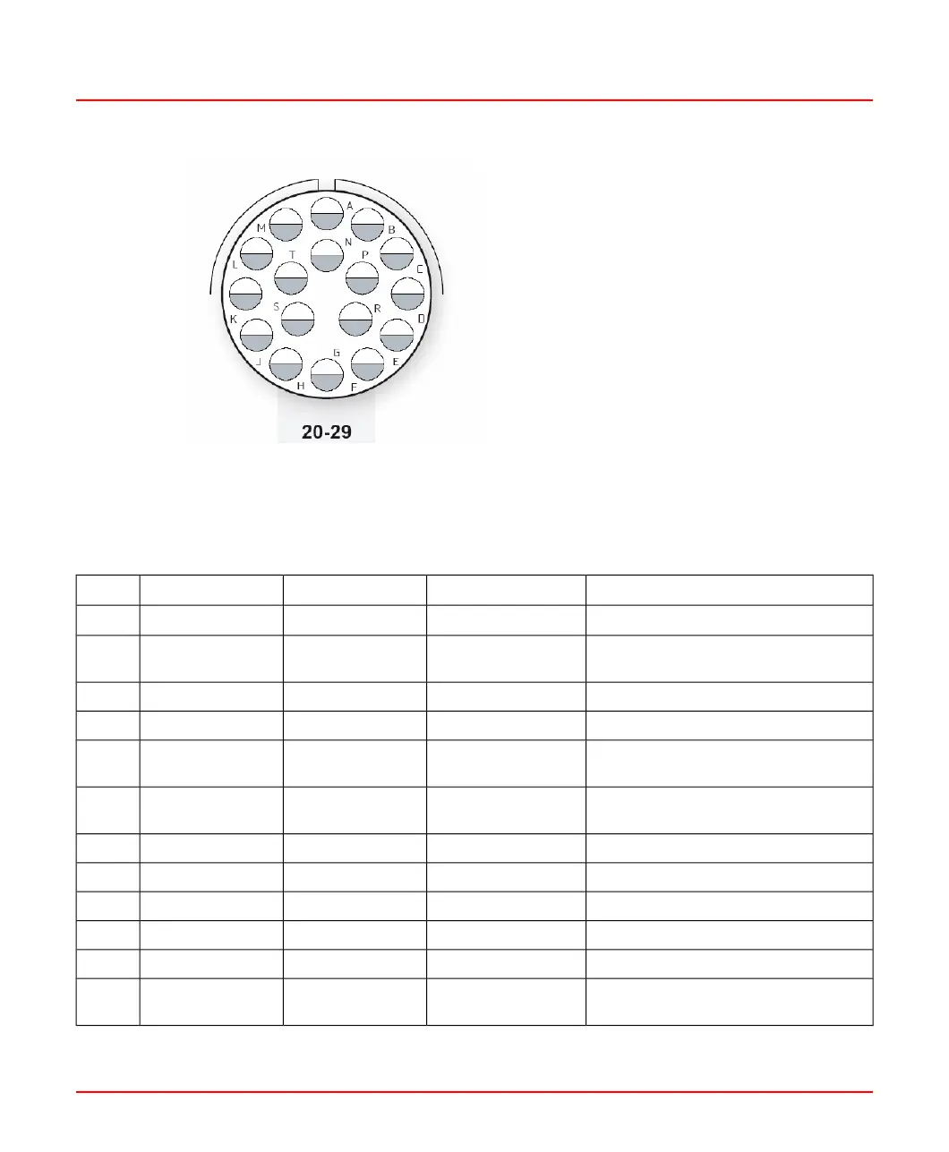
Figure 3.7: External View of Connector Pin-out (Socket) in SF910i
Table 3.2: Connector Pin Assignment and Internal Wiring for SF910i
DescriptionSignal Name
Section mm
2
Wire ColorPin
Power supply positive input+24V
DC
0.5RedK
Return of power supply, ground
reference for all internal electronics
GND0.5BlackL
Analog output (4-20mA) positiveAO+0.25White/RedM
Analog output (4-20mA) negativeAO-0.25White/BlackN
Serial communication port, data TX/RX,
positive
D+0.25GreenD
Serial communication port, data TX/RX,
negative
D-0.25RedE
Ground ref. for serial comm. PortGNDTinned copperGreen/Light blueF
Safe-relay contact (NO)Safe-relay contact0.5GreenA
Safe-relay contact (NO)Safe-relay contact0.5RedB
Flame-relay contact (NO)Flame-relay contact0.5OrangeP
Flame-relay contact (NO)Flame-relay contact0.5PinkS
Earth connection point for the shields
of the cable(s)
ShieldTinned copperGrayT
8VZZ005286 B 53
3 Installation
3.3 Product Installation