20
Zenith ZBTS T-series 100-1200A, INSTALLATION AND OPERATING INSTRUCTION
1
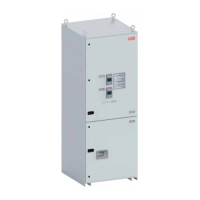
The upper switch is the Bypass switch. It
can be fixed or draw-out version. In this
manual the Bypass switch is fixed. The
lower switch, ATS, is always draw-out
version.
1 Main connections
2 Fixed Bypass, I/O connections
3 Fixed Bypass, control voltage
connectors
4 Draw-out ATS, Connection Module,
control voltage and I/O connections
5 Control Plate, front side, see back
side on previous page
6 Generator start/stop terminals
7 Aux. voltage for Ekip modules / HMI
2.2.3 Interlocks
Automatic transfer switches are electri-
cally interlocked to prevent switches from
being operated to different sources at
the same time. The doors are mechani-
cally interlocked with draw-out switch
versions so that the doors do not open
when the switch is energized or in Con-
nected/Test locations. If the Bypass
switch is fixed, then there is no mechani-
cal interlock on the upper door.
The system provides the ability to with-
draw the ATS (or the Bypass switch, if it is
the draw-out version) for test and / or
maintenance purposes without interrupt-
ing the load. During operation, the con-
tacts of Bypass switch are closed parallel-
ing the ATS contacts, which then allows
withdrawal of the ATS to the “TEST” or
“ISOLATE” locations. The systems include
mechanical and electrical interlocks that
prevent cross-service.
—
Fig. 2.8 Bypass-Isolation Automatic Transfer Switch
1
2
3
4
5
76

 Loading...