2
82
Zenith ZBTS T-series 100-1200A, INSTALLATION AND OPERATING INSTRUCTION
—
8.2 Wiring routes of I/O-connections / Ekip -modules
inside the cabinet
Once all the afterwards added or factory
installed Ekip -modules are on the right
places in fixed Bypass or in Connection
Module of draw-out switches, you need to
add the connections to the modules.
Below is one example of wiring from a
switch to Control Plate.
—
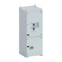
Fig. 8.5 Wiring routes for Ekip-modules in
Bypass-Isolation Automatic Transfer Switch
1 Continue the connections on the
right side of the housing in the same
way as the HMI cable.
2 Insert the wires into the same hole as
the HMI cable.
3 Attach the cables to the wall beam,
there are holes from top to bottom
and a free route for cables.
NOTE! Attach the cables if necessary.

 Loading...