19
34ZBTS_30-1200A rev.A / 1SCC303043M0201
1
—
2.2 Main and Control Connections
—
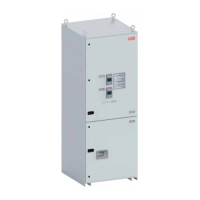
Fig. 2.6 Cable lugs for Source 1, for Source 2 and
for Load on the top module of enclosure
2.2.1 Main Connections
The top module of enclosure is for cable
lugs for Source 1, for Source 2 and for
Load. The lugs are located behind trans-
parent covers.
1 Cable lugs for Source 1
2 Cable lugs for Source 2
3 Cable lugs for Load
See mounting instructions, Part 2, chap-
ter 7.
2.2.2 Control Connections
The lowest module of enclosure, the Con-
trol Plate, is for control connections. The
customer connections such as “Gen.
Start/Stop” are on the Control Plate
(front side) and have terminal blocks for
very easy access. See next page where
the front side is described, see Fig. 2.8.
The back side of the Control Plate is de-
scriped in the Fig. 2.7.
1 Terminals for internal use
2 Protection devices
3 Transformers
4 Power Supply
5 Service terminals
6 PCBA
—
Fig. 2.7 Control Plate, back side
1 2 3
31 2 4 5 6

 Loading...