Accsense VersaLog Data Loggers User’s Manual Page 10
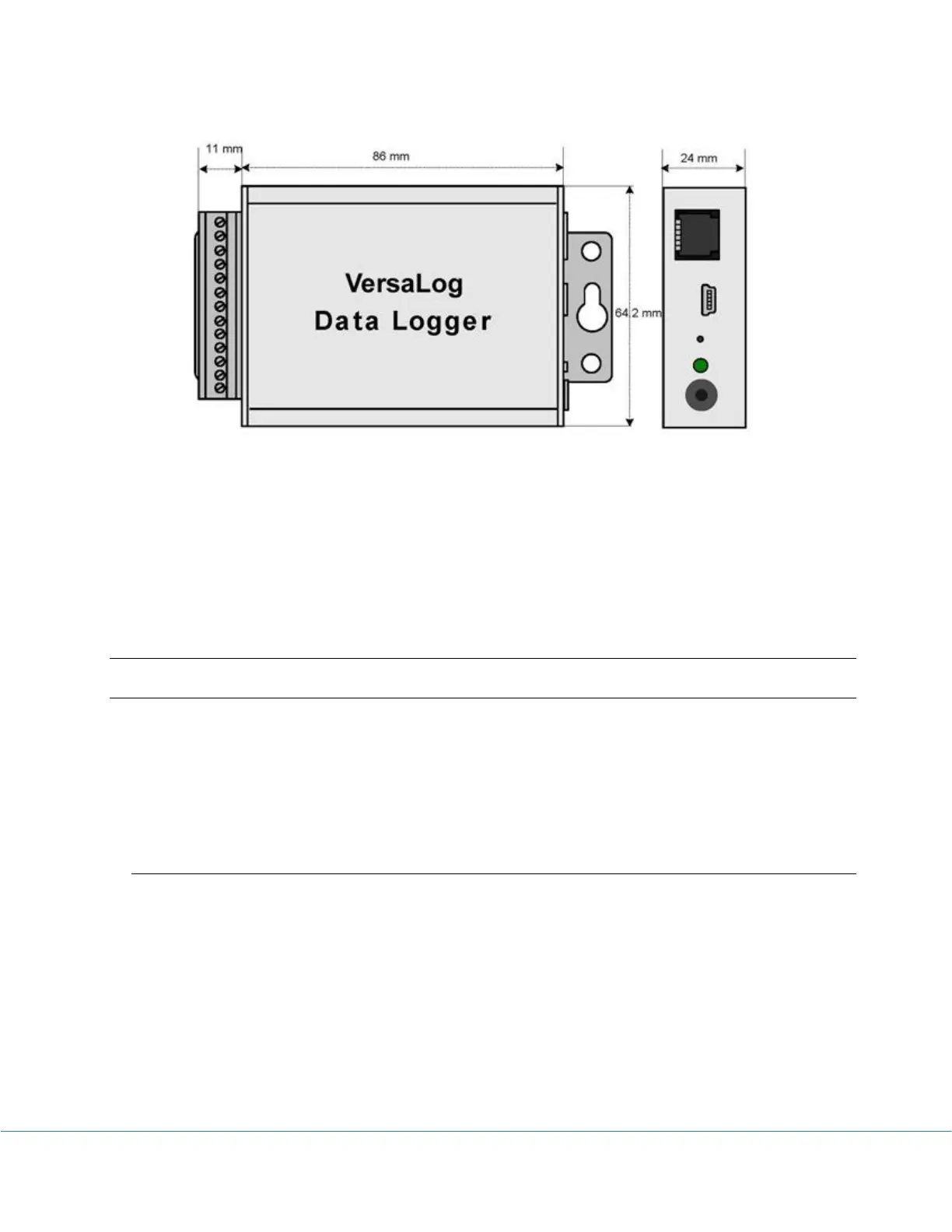
Dimension: 88 X 64.2 X 24 MM
3.46 X 2.53 X 0.95 Inches
3
3
.
.
C
C
h
h
a
a
n
n
n
n
e
e
l
l
s
s
a
a
n
n
d
d
S
S
e
e
n
n
s
s
o
o
r
r
c
c
o
o
n
n
n
n
e
e
c
c
t
t
i
i
o
o
n
n
s
s
All Accsense VersaLog data loggers have one on-board thermistor located beside the status
LED.
All “COM” terminals are connected together and should be connected to the common ground of
the process signals.
VL-DCV-2 – Voltage Inputs, Programmable Range
Besides the on-board thermistor channel, the VL-DCV-2 logger has seven external voltage DC
channels used to measure single-ended voltage DC signals maximum of 20 volt. The following
figure illustrates the correct input connections: