Accsense VersaLog Data Loggers User’s Manual Page 13
CH1
A2/E
A1
COM
CH7
CH6
COM
CH5
CH4
COM
CH3
CH2
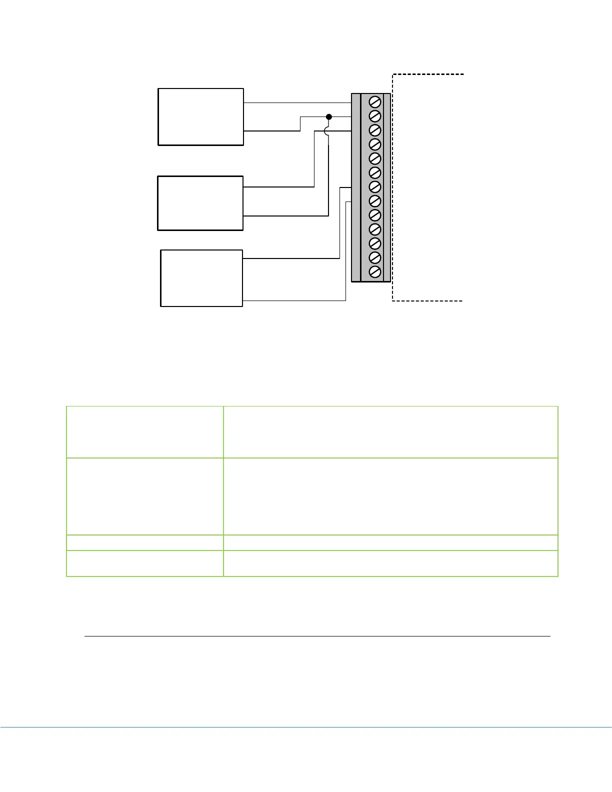
COMTransducer #1
VDC
GND
Transducer #2
VDC
GND
Transducer #3
Current DC
GND
Voltage and Current External Input Connections
Note: All inputs must share the same common ground.
Channel and Sensor Specifications:
CH1 ~ CH4 (voltage): programmable range for each channel:
0 ~ 20 V, 0 ~ 2 V.
CH5 ~ CH7 (current) programmable range for each channel:
0 ~ 20 mA.
Reference Temperature : 0.36°F
Voltage channels:
+/- 0.05% FSR @ 25°C for 20V channels
+/- 0.1% FSR @ 25°C for 2V channels
Current channels:
+/- 0.15% FSR @ 25°C
For current channel: 12 Ohms
Voltage channel: +/- 40 VDC
Current channel: +/-100 mA
VL-DCVC – Voltage & Current Inputs, Range Programmable
Besides the on-board thermistor channel, the VL-DCVC logger has seven external voltage and
current channels. The first four external channels are used to measure single-ended voltage
maximum of 20 VDC and the remaining three external channels are used to measure single-