Accsense VersaLog Data Loggers User’s Manual Page 25
Channel and Sensor Specifications:
CH1 – Excitation sense input
CH2 - ±8 mV input range
Excitation Voltage Output
2.5VDC (Max load current: 10mA)
VL-P – State/Event/Pulse Inputs, Range Programmable
VersaLog P is a 7-channel, battery powered, stand-alone pulse/state/event data logger. The
logger detects electronic or mechanical pulse counts, state changes or events in any of the seven
channels. Data is stored in non- volatile flash memory for later retrieval. It works with
gas/water/power meter, rain gauge, flow rate meter and any other digital signal/switch closure
output devices.
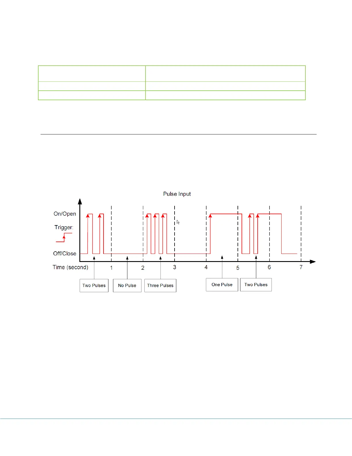
State channel is used to detect a state changes. It records the time stamp when a state changed from
Off/Close to On/Open and from On/Open to Off/Close . The resolution of the time stamp is the
sampling interval. i.e. if a state changed more than once during a sampling interval period only the
first state will be recorded (the third period in the diagram below). A typical application is to
monitor how long a device is on and off.