Accsense VersaLog Data Loggers User’s Manual Page 33
Note: The activation button cannot be further activated once the logger has started the new
session.
Status LED
The Accsense VersaLog logger has an on-board LED used to indicate:
1. Sampling:
When the LED was enabled by Accsense VersaLog, it will flash once in green when the
logger is sampling. The colour of the LED can be overridden by the following conditions:
2. Alarms:
The LED will flash red when it samples if any channel alarms are enabled and are
triggered.
3. Low Battery:
The LED will flash in amber when it samples if the logger detects a low battery level.
If you do not need the LED to indicate the status of operation you can disable it (via Accsense
VersaLog) in order to increase the battery life.
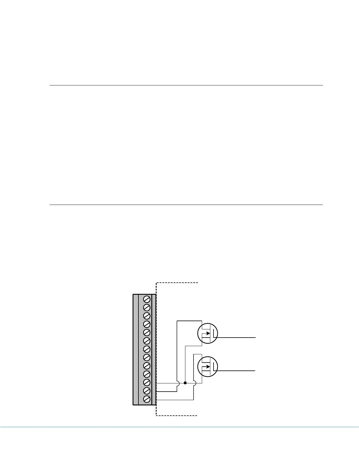
Alarm1 & A2/EXT Terminals
Alarm1 and A2/EXT terminals internally connect to the on-board N-channel MOSFET
switches. They can be used to control an external power supply to turn on/off devices like lamp,
strobe light or siren, or coil relays. The maximum power the switches can supply is 200mA @
24VDC.
The internal schematics of the switches are as follows:
CH1
A2/E
A1
COM
CH7
CH6
COM
CH5
CH4
COM
CH3
CH2
COM
Control 1
Control 2