AccuAir Rocker Switch Manual V2.7 © 2007 AccuAir Control Systems, L.L.C.
- Page 18 -
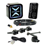
Height Sensor Installation:
Step 6.) With the sensor linkage
installed on the sensor arm and the
vehicle at the middle of the travel,
hold the sensor apparatus up as if it
were attached to the ball stud that you
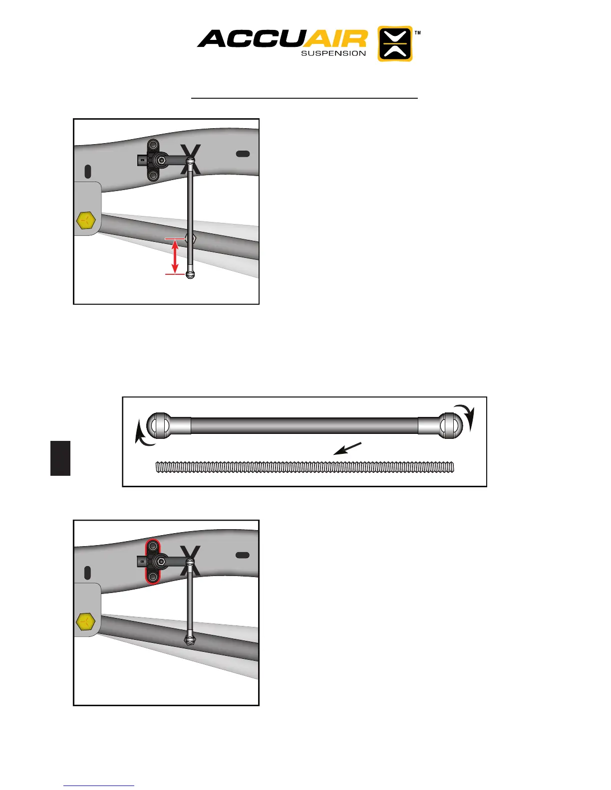
installed in Step 5. Determine if you will
need to shorten the linkage. If not con-
tinue to step 8. If so unscrew the end-
links and cut the threaded rod, (Make
sure to restart the threads nicely). Then
cut the plastic tubing 5/8” shorter then
your new total rod length, (you want
5/16” worth of thread engagement
on each end). Then re-assemble the
rod. Note that the end links do not need to get tight on the rod, because once
installed the ball stud prevents them from rotating loose.
Step 7.) Attach the lower end-link to the
ball stud. With the vehicle about half
way through the travel, nd the exact
sensor mounting point that keeps the
mounting holes and linkage rod vertical.
Once established, trace the outline of
the sensor to the frame.
Metric
6 mm x 1.0