AccuAir Rocker Switch Manual V2.7 © 2007 AccuAir Control Systems, L.L.C.
- Page 19 -
Height Sensor Installation:
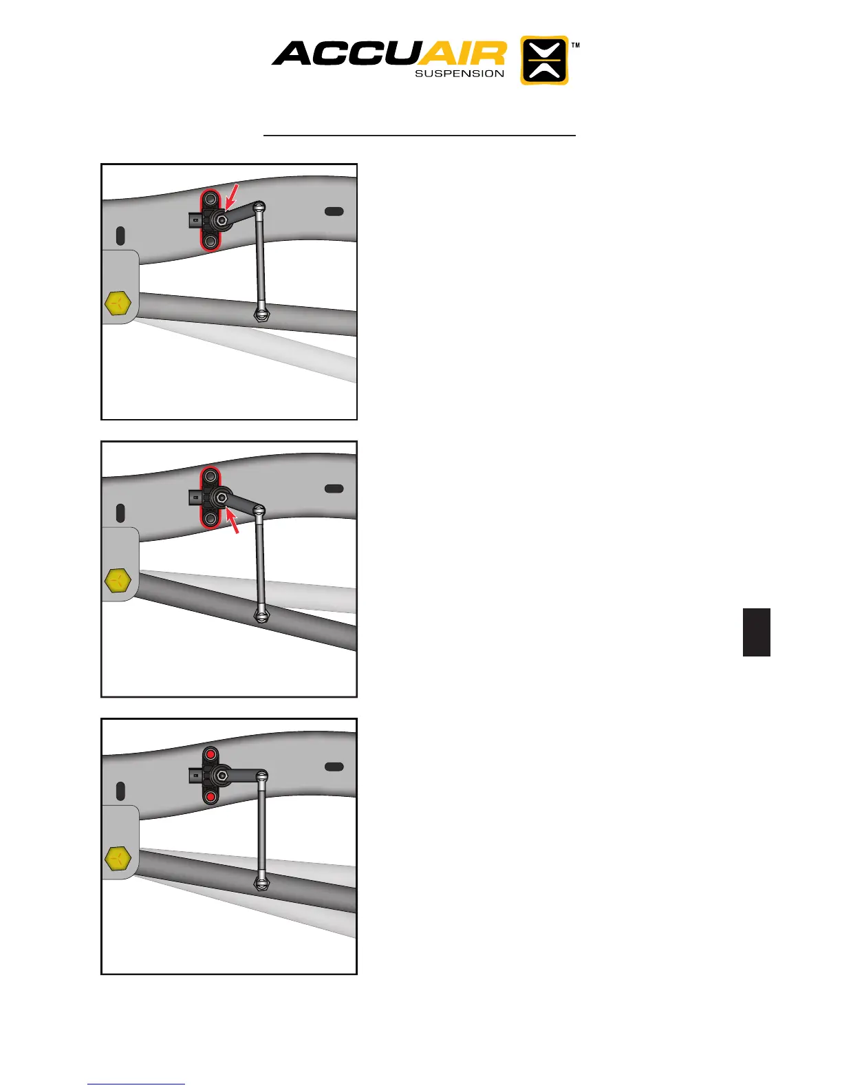
Step 8.) With the vehicle at the very
bottom of the travel, hold the sensor at
the same location traced on the frame
in step 7. Either rotate the sensor slight-
ly, or adjust the linkage so that there is
about 1/4” of clearance between the
upper plastic stop and the rotating arm.
Visually note this amount.
Step 9.) With the vehicle at the very
top of the travel, compare the clear-
ance found in step 8, to the clearance
between the lower plastic stop and the
rotating arm. Repeat Step 8 and 9 until
the upper and lower clearance is ap-
proximately equal.
Step 10.) Use the nal sensor loca-
tion to mark the two mounting holes to
be drilled through the frame. Drill the
holes and install the sensor mounting
hardware. (BE CAREFUL NOT OVER
TIGHTEN!)
Step 11.) Now that the sensor is mount-
ed, repeat Step 8 and Step 9 to make
sure that the clearance is still equal.
Adjust the linkage if necessary.