www.accuenergy.com
V: 1.0 Revised: Jan. 2018
19
Chapter 2: Installation - Physical Setup
Digital Input
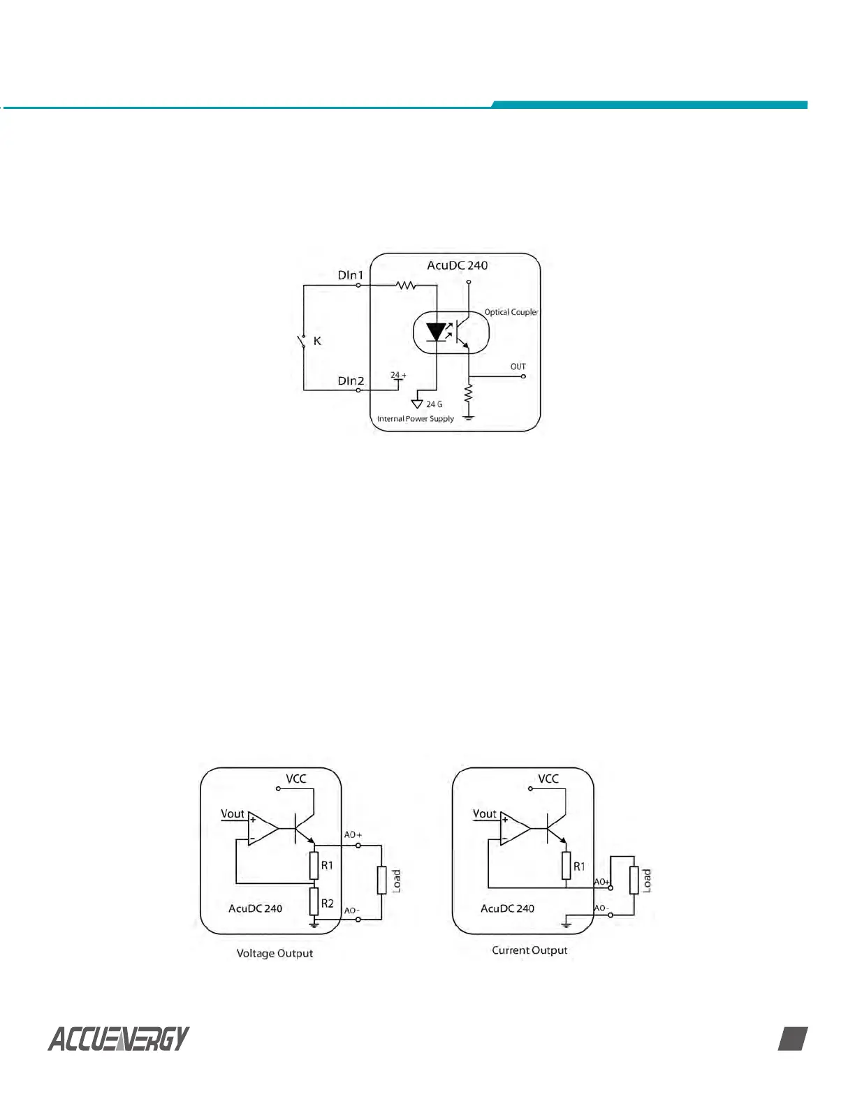
AcuDC 240 optional I/O module is equipped with two dry contact digital inputs. The
terminals are (17), (18), (19) and (20), as shown in figure 2-7. The Circuit is simplified as:
When the switch is open, there is no current flowing into the diode side of the optical
coupler, the triode is off, OUT is in low state. When the switch is closed, there is current
flowing into the diode side, the triode is on, OUT is in high state. In this way, the ‘high’ and
‘low’ state of OUT corresponding to ‘closed’ and ‘’open’ state of the switch.
The I/O module has built in power supply therefore the digital input does not require an
external power supply.
DI wire may choose AWG22-16 or 0.5-1.5 mm
2
.
Analog Output
AcuDC 240 I/O module offers two Analog Output modes, which are the current output
0-20mA/4-20mA(max 24mA) mode, and the voltage output 0-5V/1-5V(max 6V) mode, as
shown in figure 2-15.
NOTE: Each module can only has one type of output, please specify when ordering.
Fig 2-15 Analog Output Wiring
 Loading...


