www.accuenergy.com
V: 1.0 Revised: Jan. 2018
83
Appendix
C. Ordering Information
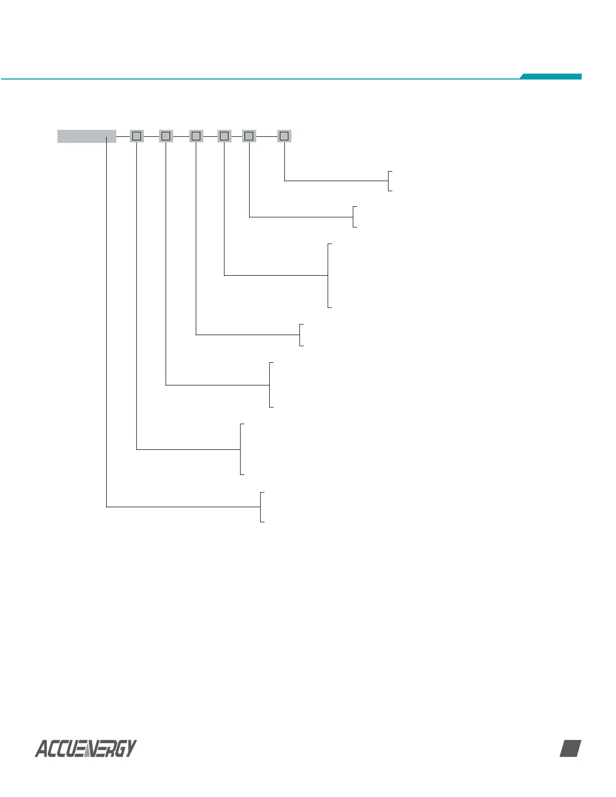
AcuDC 240
Model
AcuDC 241: Voltage Meter
AcuDC 242: Current Meter
AcuDC 243: Multifunction
Voltage Option
1000V: Nominal Input Voltage 1000Vdc
600V: Nominal Input Voltage 600Vdc
300V: Nominal Input Voltage 630Vdc
60V: Nominal Input Voltage 60Vdc
5V: Nominal Input Voltage (0-5V/0-4V), ratio settable
Current Option
A0: 0~±10A
A1: Shunt (50~100mV)
A2: Current Hall Effect Sensor (4~20mA/12mA±8mA)
A3: Voltage Hall Effect Sensor (0~±5V/0~±4V)
Power Supply Option
P1: 100-240Vac 50/60Hz, 100-300Vdc
P2: 20-60Vdc
I/O Option
X0: No I/O
X1: 2DI+2AO (4~20mA/0~20mA)
X2: 2DI+2AO (0~5V/1~5V)
X3: 2DI+2RO
X4: 2DI+2DO
X5: 2DI+ ±15Vdc
Communication
NC: No Communication
C: RS485, Modbus RTU
Datalogging
ND: No Datalogging
D: Datalogging (Acudc 243 Only)
Example: AcuDC 243 - 300 - A2 - P1 - X1 - C - D
NOTE: When the input voltage is above 1000V, or the system design requires an isolation
sensor, the voltage input can be selected as Via Hall Effect Sensor (0~5 V). The Voltage Hall
Effect Sensor output range requires 0~5 V.
 Loading...


