www.accuenergy.com
V: 1.0 Revised: Jan. 2018
66
AcuDC 240 Series
DC Energy & Power meters
B.2 Communication Format
This section will illustrate the format indicated in Table B-3.
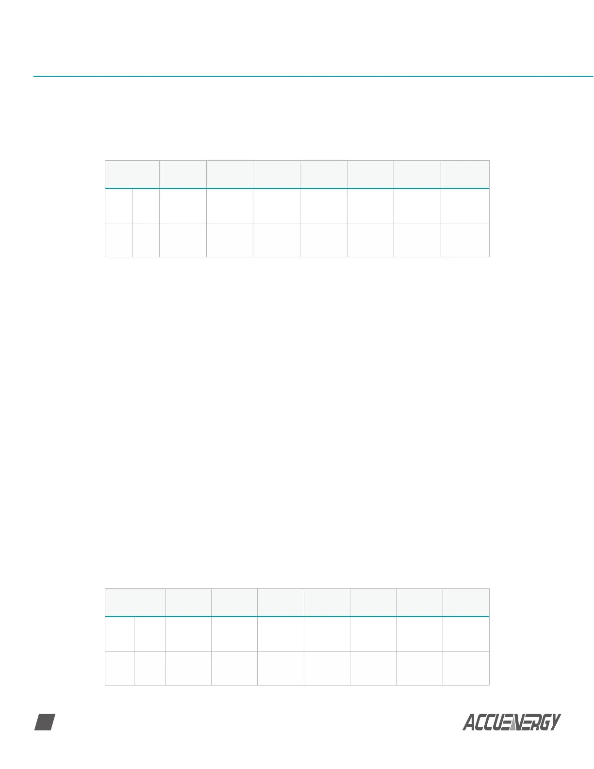
Table B-3 Protocol Illustration (Hex value and Decimal value)
Addr: Slave device address
Data start reg hi: Start register address, high byte
Data start reg lo: Start register address, low byte
Data# of reg hi: Number of registers, high byte
Data# of reg lo: Number of registers, low byte
CRC 16 hi: CRC high byte
CRC 16 lo: CRC low byte
B.2.1 Read Relay Output Status (Function Code 01)
Query
The master device sends query frame to the slave device. Function Code 01 allows users
to acquire the relay output status (1=ON, 0=OFF) of the slave device with the specified
address. Along with slave device address and function code, query frame must contain
the relay register starting address and the number of registers to be read.
AcuDC 240 relay output address starts from 0000H (Relay 1=0000H, Relay 2=0001H).
Table B.4 depicts reading Relay 1 and 2 statuses from slave address 17.
Table B-4 Query Frame of Reading Relay Output Status
Addr Fun
Data Start
Reg Hi
Data Start
Reg Lo
Data # of
Regs Hi
Data # of
Regs Lo
CRC16 Hi CRC 16 Lo
Hex
06
H
03H 00H 00H 00H 21H 84H 65H
Dec 6 3 0 0 0 33 132 101
Addr Fun
Data Start
Reg Hi
Data Start
Reg Lo
Data # of
Regs Hi
Data # of
Regs Lo
CRC16 Hi CRC 16 Lo
Hex 11H 01H 00H 00H 00H 02H BFH 5BH
Dec 17 1 0 0 0 2 191 91
 Loading...


