www.accuenergy.com
V: 1.0 Revised: Jan. 2018
20
AcuDC 240 Series
DC Energy & Power meters
2.3.5 Communications Wiring
AcuDC 240 series meter uses RS485 serial communication and the Modbus RTU protocol.
The terminals of communication are A, B and S (14, 15 and 16). A is differential signal +, B is
differential -, and S is connected to the shield of twisted pair cable. The overall length of
the RS485 cable connecting all devices cannot exceed 1200m (4000ft). Utilizing a large
number of RS485 devices and utilizing a high baud rate will make the communication
range shorter. AcuDC 240 works as a Slave device. Master device can be PC, PLC, Data
Acquisition Device, or RTU.
Suggestions to improve communication quality:
A high-quality Shielded Twisted Pair cable, AWG22(0.6mm2) or larger diameter cable, is
recommended. Two cables should be in different colors.
• Pay attention to ‘single point earthling’. Make sure that there is only one point of the
shielding connected to ground in a single communication link.
• Every terminal A(+) should be connected to terminal A(+), terminal B(-) to terminal B(-
), or it will influence the network, or even damage the communication interface.
• The connection topology should avoid ‘T’ type which means there is a new branch
and it does not begin from the beginning point.
• Keep communication cables away from sources of electrical noise whenever possible.
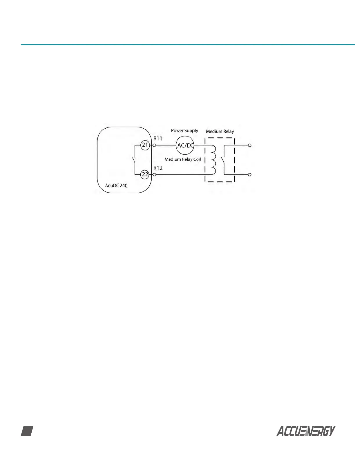
Relay Output
The AcuDC 240 series I/O option has two relay outputs, which are terminal (21), (22) and
(23), (24) as shown in Fig 2-7. They can be used to remotely control circuit breakers.
The relay outputs are form A (normally open) electromagnetic relay. The nodal capacity is
3A/250 Vac or 3A/30Vdc. If the coil current is high, a medium relay is recommended.
 Loading...


