www.accuenergy.com
V: 1.0 Revised: Jan. 2018
28
AcuDC 240 Series
DC Energy & Power meters
Refer to section 3.2.2 configure AcuDC to work with Hall Effect
Sensor, first set the full range current setting as shown in Fig
3-2. Press ‘F’ and ‘V/A’ simultaneously whiles in the metering
display mode to get to the system parameter setting mode. In
the parameter setting mode, Press ‘V/A’ until you get to the ‘I In’
screen as shown in Fig 3-2. Enter the rated current input of the
shunt in this screen. After setting up the current range, press
‘V/A’ until the screen ‘I P’ displays. This setting corresponds to the
output range of the Hall Effect Sensor. Press ‘F’ to change this
setting and to select required output. Press ‘V/A’ to confirm this
setting; the cursor will stop flashing at this point.
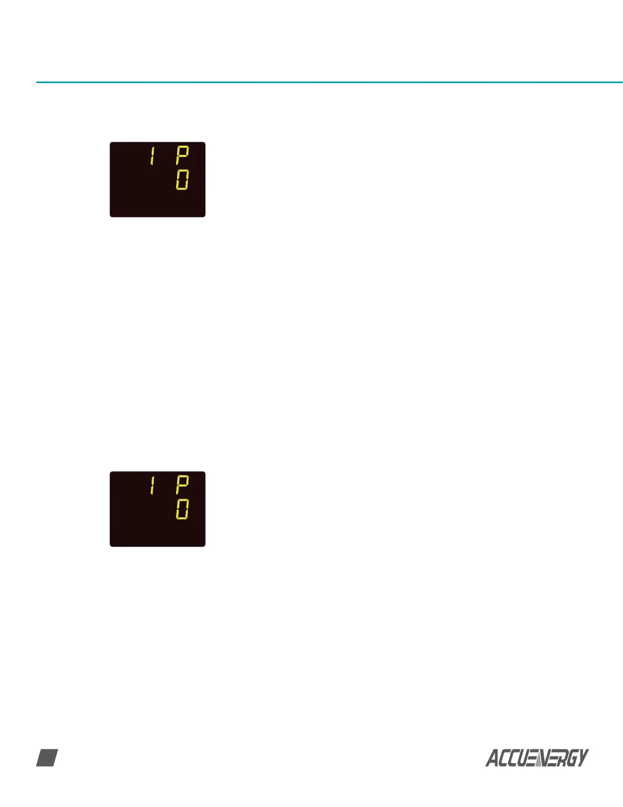
After setting up the current range, press ‘V/A’ to go to the next
screen, as shown in Fig 3-5. This will be the ‘I P’ screen. This
setting corresponds to the output range of the current Hall
Effect Sensor. Press ‘F’ to change this setting and to select
required output. Press ‘V/A’ to confirm this setting; the cursor will
stop flashing at this point.
Fig 3-4 Current Hall
Effect sensor setting
Fig 3-5 Current Hall
Effect sensor setting
SET
SET
NOTE: The default setting is ‘0’ for 4~20mA/0~±5V. The other mode is ‘1’ for
4-12~20mA/0~±4V.
3.2.4 Configure AcuDC to work with Current and Voltage Hall Effect Sensor
If the meter is wired to measure current and voltage using a current hall effect sensor and
voltage hall effect sensor respectively, You need to configure the settings in the AcuDC so
that it can read accurately from both Hall Effect Sensors.
Refer to section 3.2.2 configure AcuDC to work with shunt, first set up the current input
range as shown in Fig 3-2 full range current setting.
NOTE: The default setting is ‘0’ for 4~20mA/0~±5V. The other mode is ‘1’ for
4-12~20mA/0~±4V.
 Loading...


