www.accuenergy.com
V: 1.0 Revised: Jan. 2018
Chapter 3: Installation - Conguration Parameter Set-up
31
Press ‘F’ and ‘V/A’ simultaneously whiles in the metering
display mode to get to the system parameter setting mode. In
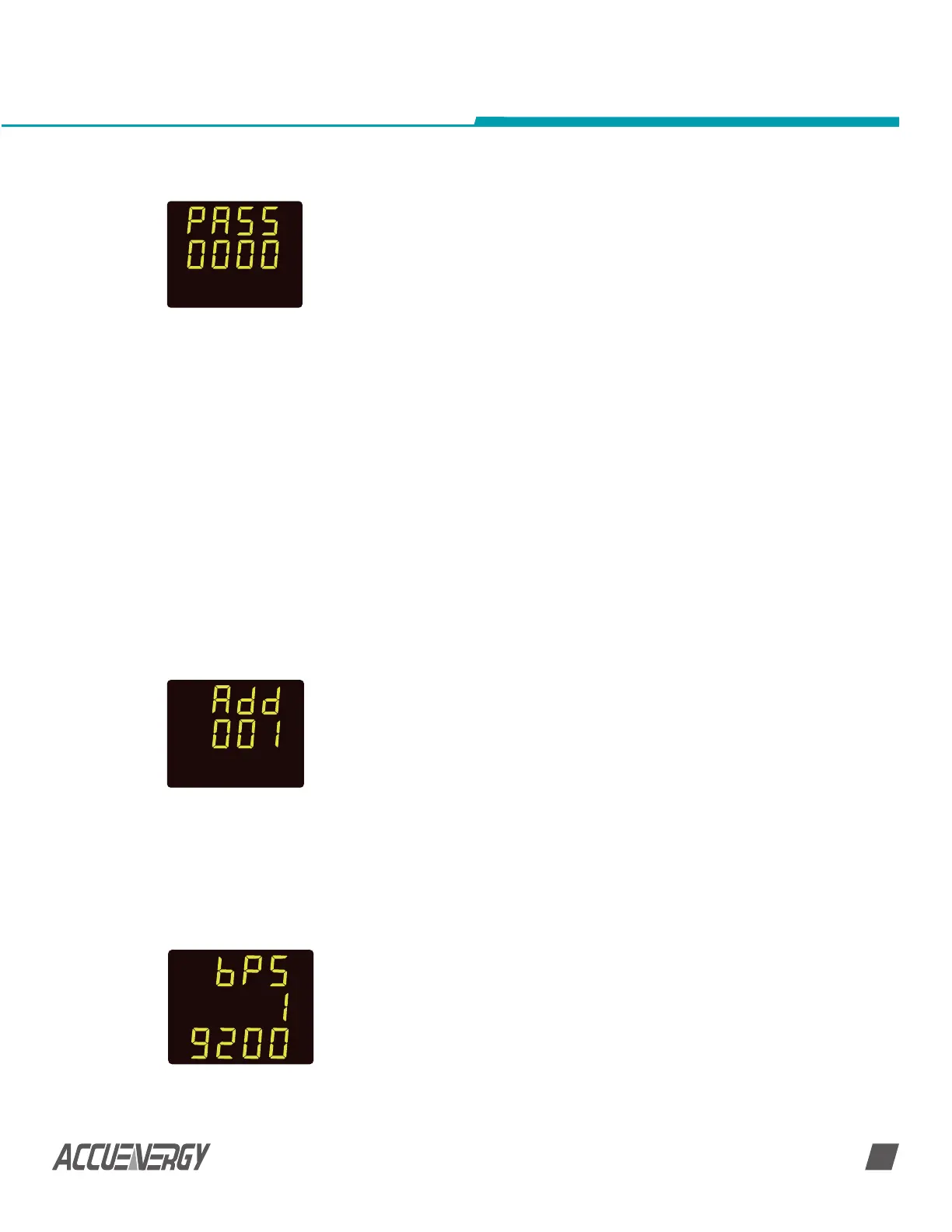
parameter setting mode, press ‘V/A’ until you get to the ‘PASS’
screen, as shown in Fig 3-14. Press ‘F’ to change this setting. A
digit will begin to flash and you can change the number. Press
‘F’ to increase the value of the flashing digit. Press ‘V/A’ to switch
the flashing digit. Press ‘V/A’ when on the last digit to confirm
the change; the cursor will stop flashing at this point. Press ‘V/A’
to confirm and go to the next screen.
Communication address can be any integer 1 ~ 247. Fig 3-15
shows the address number is 1. Press ‘F’ to change this setting.
The first digit will begin to flash and you can change the edit
mode. Press ‘F’ to increase the value of the flashing digit. Press
‘V/A’ to switch the flashing digit. Press ‘V/A’ when on the last
digit to confirm the change; the cursor will stop flashing at this
point. Press ‘V/A’ to confirm and scroll to the next screen.
After address setup, the second screen is Baud rate setting
page, or in parameter setting mode, press ‘V/A’ until see ‘bPS’
on the screen. Baud rate can be set as 1200, 2400, 4800, 9600,
19200 and 38400. Fig 3-18 shows the baud rate is 19200 bps.
Press ‘F’ to select the desired baud rate, and then press ‘V/A’ to
confirm and go to the next screen.
Fig 3-14 Password
Setting
Fig 3-15
Communication
Address Setup
Fig 3-16 Baud Rate
Setting
By now the parameter settings are almost completed, except for the I/O module setting.
Pressing ‘F’ and ‘V/A’ simultaneously will exit system parameter settings mode and return
to the metering data mode.
3.2.8 Password Setting
SET
3.3 AcuDC Communication Setup
NOTE: Only meters with communication options have device address, baud rate and
parity setting screens.
To set communication parameters from the meter display mode, you must first press
the ‘F’ and ‘V/A’ buttons simultaneously to get to the parameter setting mode. The
communication parameter setup includes address setup, Baud rate setup, and parity
setting, as shown in table 3-3.
NOTE: Modbus-RTU communication protocol requires that all meters on the same
communication bus should have different addresses.
SET
SET
 Loading...


