www.accuenergy.com
V: 1.0 Revised: Jan. 2018
67
Appendix
Response
The slave device answers the master device’s query. The response frame contains slave
device address, function code, data quantity and CRC check. Each relay utilizes one bit
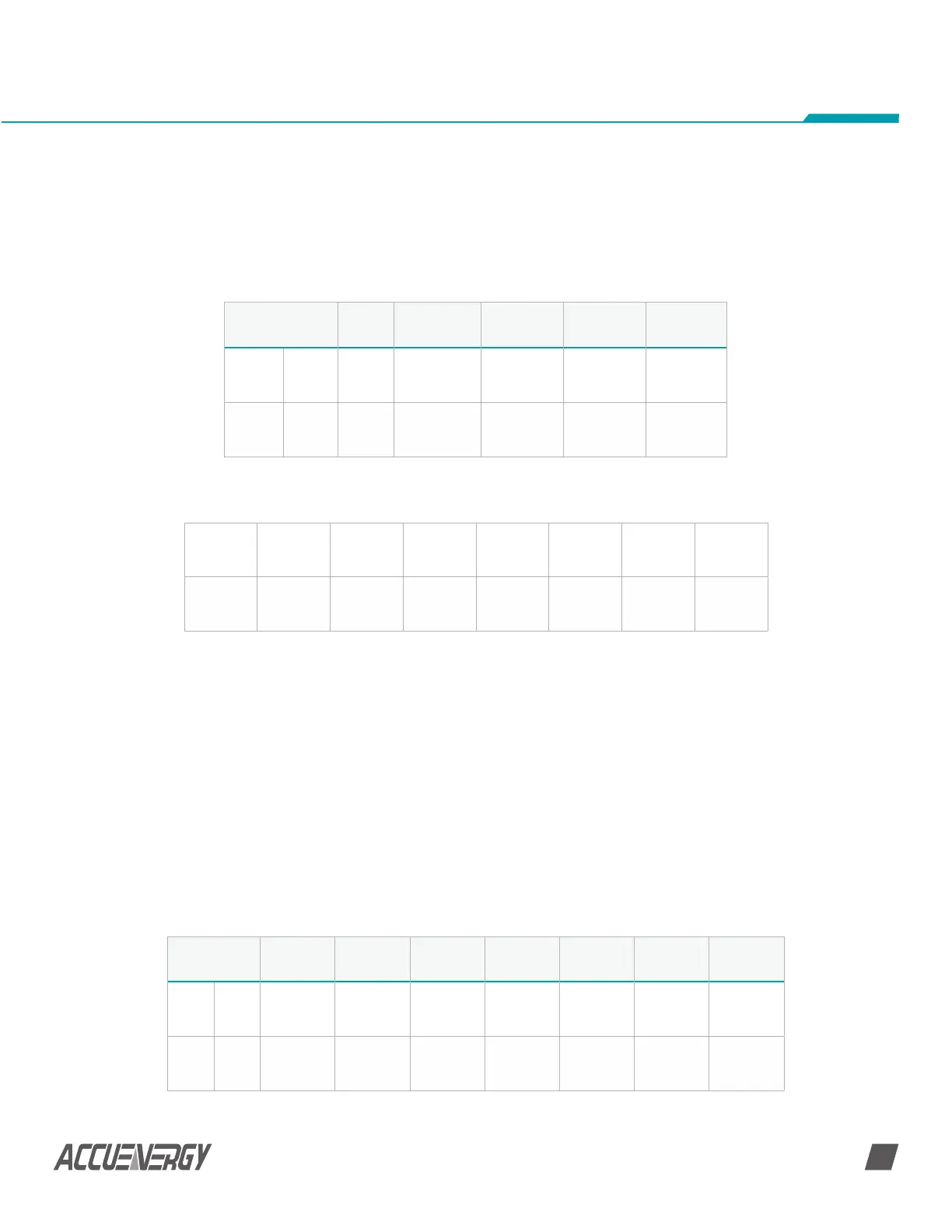
(1=ON, 0=OFF). Table B-5 depicts the response frame.
Table B-5 Response Frame of Reading Relay Output Status
Data Bytes
(Relay 1=OFF, Relay 2=ON)
B.2.2 Read DI Status (Function Code 02)
Query
This function allows the user to obtain DI status ON/OFF (1=ON, 0=OFF). On top of slave
device address and function code, query frame must contain the digital input register,
starting address and the number of registers to be read. AcuDC 240 DI address starts
from 0000H (DI1-0000H, DI2-0001H).
Table B.6 depicts reading DI1 to DI2 status of the slave device with the address of 17.
Table B-6 Query Frame of Reading DI Status
Addr Fun Byte Count Data CRC16 Hi CRC 16 Lo
Hex 11H 01H 01H 02H D4H 89H
Dec 17 1 1 2 212 137
7 6 5 4 3 2 1 0
0 0 0 0 0 0 1 0
Addr Fun
Data Start
Reg Hi
Data Start
Reg Lo
Data # of
Regs Hi
Data # of
Regs Lo
CRC16 Hi CRC 16 Lo
Hex 11H 02H 00H 00H 00H 02H FBH 5BH
Dec 17 2 0 0 0 2 251 91
 Loading...


