www.accuenergy.com
V: 1.0 Revised: Jan. 2018
50
AcuDC 240 Series
DC Energy & Power meters
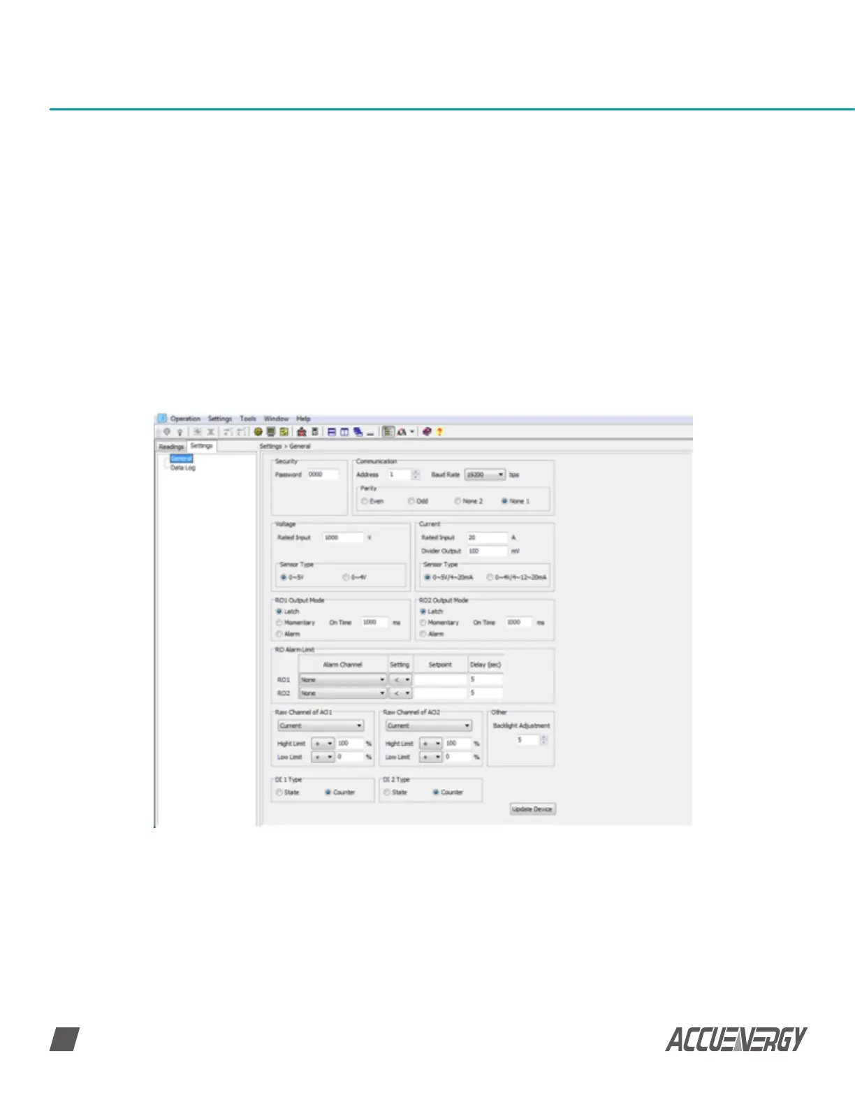
RO1 Output Mode/RO2 Output Mode: This is available with the ‘X3’ module
Choose between the three modes:
• Latch: To manually turn on and off the relay
• Momentary: To turn on the relay for a set number of seconds before it goes back off.
• If momentary mode is selected, set the delay time ‘On Time’; the range is 300-
5000ms. The delay time has an error of up to 3ms (due to the relay action time
error)
• Alarm: To trigger the relay output through an alarm event.
RO Alarm Limit: Set the Alarm Channel, Setting, Setpoint and Delay (in sec) for both RO1
and RO2; this is needed if RO1/RO2 Output mode is set as ‘Alarm’
Fig 5-4 General settings
 Loading...

