www.accuenergy.com
V: 1.0 Revised: Jan. 2018
64
AcuDC 240 Series
DC Energy & Power meters
B.1.2 Modbus Protocol
1. Frame
When data frame reaches the terminal unit, the unit removes the data frame’s header,
reads the data, if there is no error, it’ll implement the data’s task. Afterwards, the unit
puts its own data with the acquired header, and sends back the frame to the sender. The
response data frame contains: Address, Data and CRC Check. Any error will cause a failure
to respond.
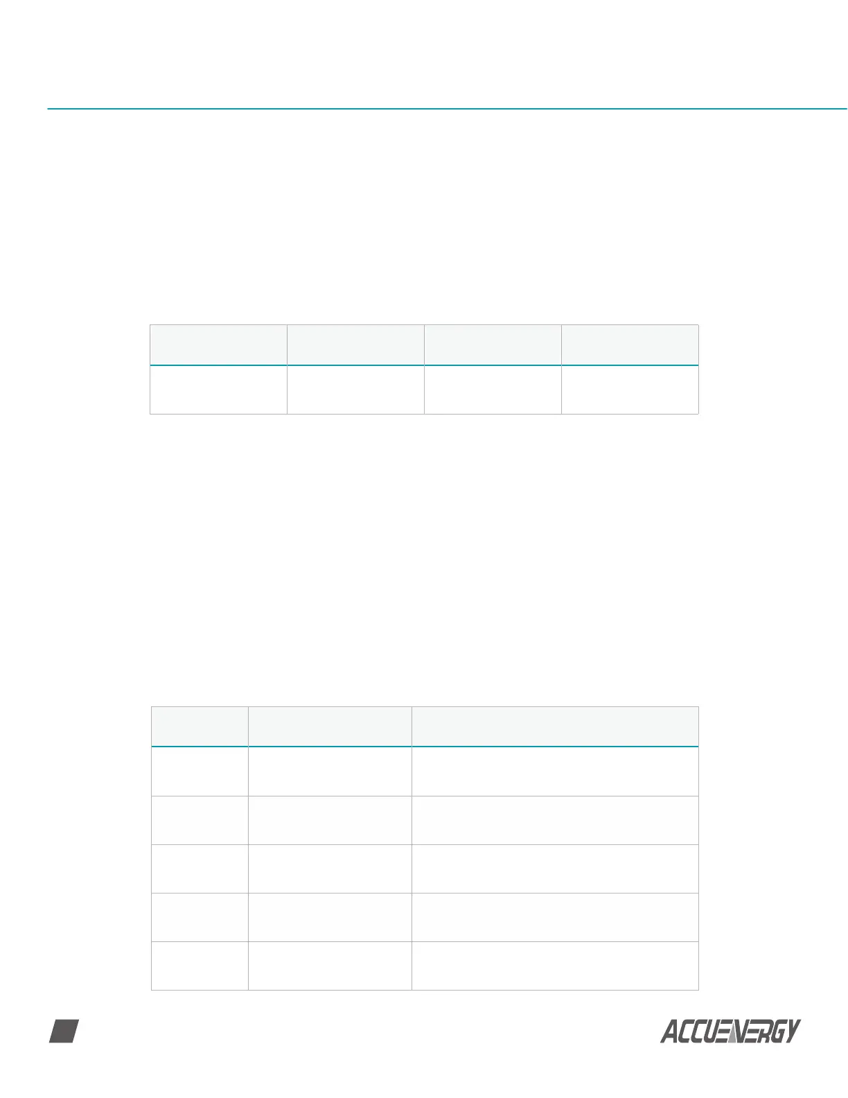
Table B-1 Data Frame Format
Address Function Data Check
8-Bits 8-Bits N X 8-Bits 16-Bits
Code Meaning Action
01 Read RO Status Obtain Relay Output Current Status (ON/OFF)
02 Read DI status Obtain Digital Input Current Status(ON/OFF)
03 Read holding register
Obtain Current Binary Value of One or Multiple
Registers
05 Control RO Control Relay Output(ON/OFF))
16 Preset multiple registers Place Specific Binary Value into Multiple Registers
2. Address Field
The address field is at the start of the frame. It is composed of 1 byte (8 bits), its decimal
value range is 0~255.
A master addresses a slave by placing the slave address in the address field of the
message. When the slave sends its response, it places its own address in this address field
of the response to let the master know which slave is responding.
3. Function Field
When a message is sent from a master to a slave device, the function code field tells the
slave what kind of action to perform.
Table B-2 Function Code
 Loading...


