33
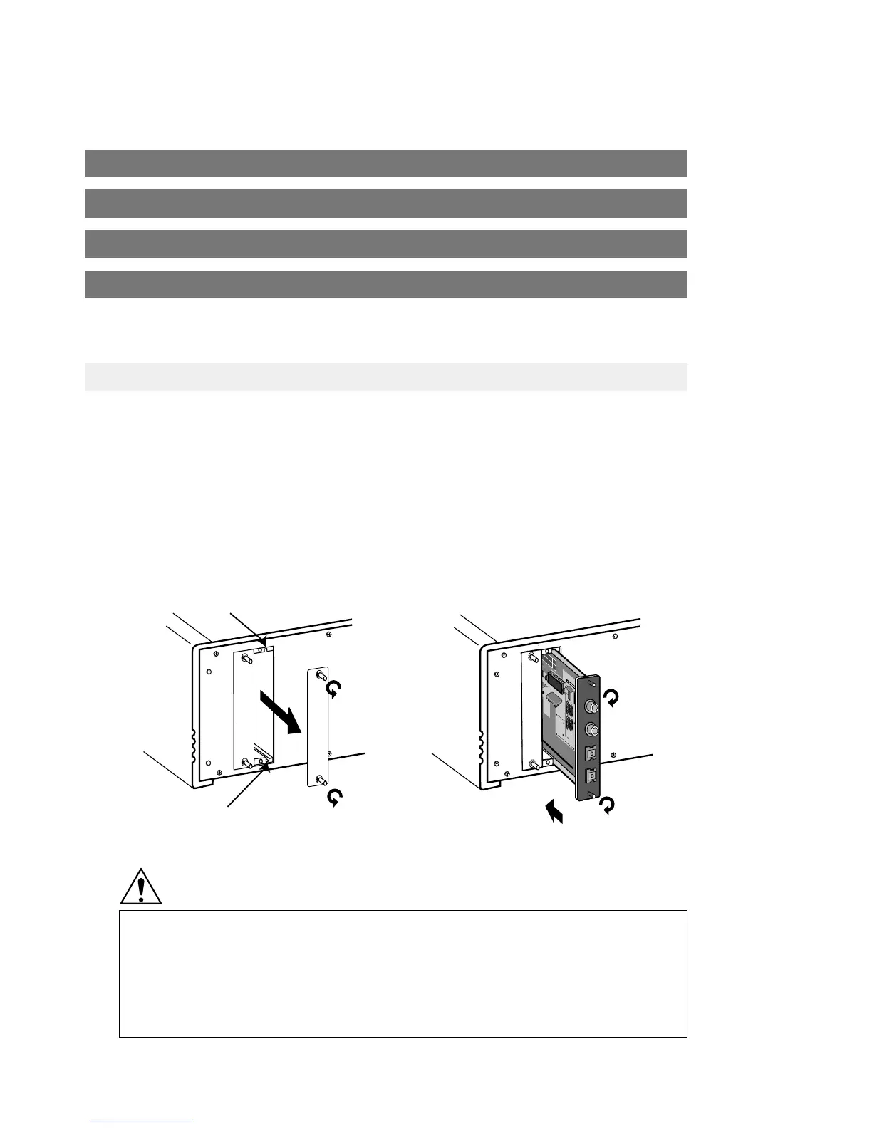
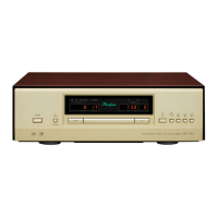
Option Board Installation
Set the power switch of the DP-77 to OFF.
Remove the panel covering the slot on the rear of the DP-77.
For dual-slot boards, remove two panels.
Insert the option board by sliding it into the top and bottom guide rails of the slot. When the board
touches the internal connector, give it a slight push until the board is firmly seated. (The board
must be flush with the panel.)
Secure the board with the two screws at the top and bottom.
●
Be sure to turn the DP-77 off before inserting or removing any option boards. Otherwise damage may
occur.
●
To prevent damage due to static discharge, do not touch the components on the board or the connector.
Grasp the board only at the PCB edges or the rear panel.
●
Tighten the two fastening screws firmly. If the screws are loose, ground connection will be impaired and
damage may occur.
CAUTION
D
I
O
-
O
C
7
2
4
-
0
0
1
9
-
0
0
D
I
O
-
C
7
2
4
-
0
0
2
0
-
0
0
IS
0
12
0A
P
9
53
21
0
1
T
O
S
H
IB
A
7
4
H
C
T
O
TOSHIBA
74HCTO
N
F
V
5
1
0
2
0
M
H
z
0
.2
4
Guide rail
Guide rail
⑪LineInputBoard(forunbalancedconnections) AI2-U1
⑫LineInputBoard(forbalancedconnections) AI2-B1
⑬LineOutputBoard(forunbalancedconnections) AO2-U1
⑭LineOutputBoard(forbalancedconnections) AO2-B1
For analog connection, installed in DG-38
*Connection examples see page 27.