Appendix 4 / Inhibit Input
The INHIBIT input allows the actuator to be turned off (inhibited) by a customer-supplied control
signal.
There are four customer-selectable INHIBIT operati
ng modes. These modes are controlled by
parameter 19. Refer to page 17 for more information about setting controller parameters.
The INHIBIT input requires an isolate
d contact closure. To activate or deactivate the INHIBIT
input, close (short) or open the connection between J7 terminals 8 and 9 (refer to the diagram
below).
Note: T
he INHIBIT input will override all Discrete Isolated inputs. To allow the Discrete Isolated
inputs to operate properly, the INHIBIT input must be inactive.
Note: The INHIBIT input is not opto-isolated. If your application requires an opto-isolated
INHIBIT input, then set parameter 72 to 1. Refer to page 17 for more information about setting
controller parameters.
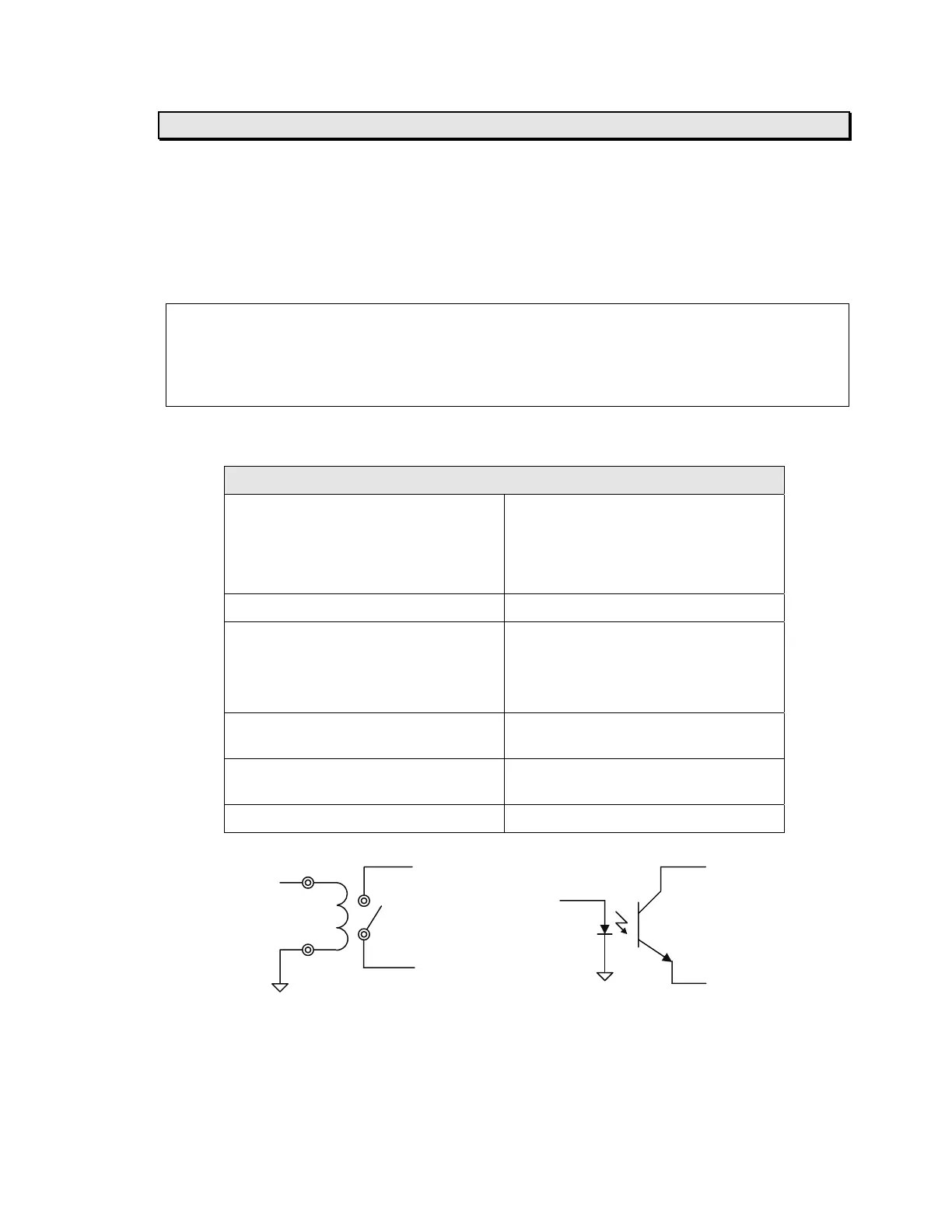
Electrical Specifications:
Non-isolated contact-closure input
Description This input must be connected to an
isolated contact or a sink-connected
(NPN) opto-coupled transistor output.
It must not be connected to anything
else.
Connector J7
Terminals 8 – Signal input (connect to collector
of customer-supplied opto-coupler)
9 – Signal GND (connect to emitter of
cu
stomer-supplied opto-coupler)
Input voltage Internally pulled to +5 VDC through a
5 K-ohm resistor
Input current 1 mA to turn on, 0.27 mA or less to
turn off
Isolation None, provided by customer
INHIBIT J7-8 J7-8
Signal INHIBIT
Signal
J7-9
J7-9
Relay Control Solid State Control
MICRO 4000
NET Controller
45
Artisan Technology Group - Quality Instrumentation ... Guaranteed | (888) 88-SOURCE | www.artisantg.com