5-22 WORKING WITH THE CONTROL UNIT
SB1391 Hardware and Setup Guide - Document revision no. 1.14
Action Effect of action
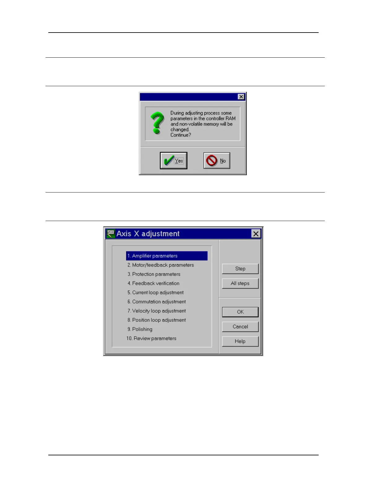
1. From the Adjust menu, select the
axis to adjust, for example, Axis X
(FIGURE 5-18).
Adjuster displays a warning that some of the values in
the control unit RAM may change (FIGURE 5-19).
(Leave the Partial adjustment option unchecked.)
FIGURE 5-19 Control unit warning before adjustment session
2. Click Yes. Adjuster sets the control module parameters to default
values. The Axis Adjustment dialog box appears, as in
FIGURE 5-20.
FIGURE 5-20 Adjustment steps
The Axis adjustment dialog box is the starting point for each adjustment step.
Selecting a step and clicking Step (or double-clicking the step) opens a dialog box. In the loop
adjustment steps (steps 5, 7, and 8), a "soft oscilloscope" window also opens, displaying the
control unit response as parameters are changed.