WORKING WITH THE CONTROL UNIT 5-33
SB1391 Hardware and Setup Guide - Document revision no. 1.14
Caution
Avoid setting the Current parameter outside the range 10% to 30%.
5.2.12. Step 6 - Commutation
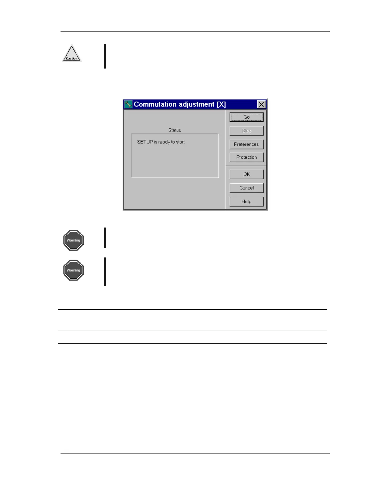
FIGURE 5-31 Commutation adjustment step
Warning
During commutation, the motor physically moves.
Warning
At this point, the phase order of the wiring is fixed. Remember to note at this
point how the motor and encoder are wired, to use as a future reference.
Action Effect of action
1.
Select 6. Commutation
adjustment and click Step.
The Commutation adjustment dialog box opens
(FIGURE 5-31).
2. Click Preferences.
The Commutation preferences dialog box opens.