Page 19
a) 8 Zone Mode:
In this mode the "Zone Buttons" 1-8 in the first 16 relay section are active
while the 9 through 16 are not. (Or it is a 16 relay card and there is no 9 to 16)
In the 8 zone mode the relay card takes up 1 address on the bus.
b) 16 Zone mode
In this mode all 16 central Zone Buttons are active.
In this mode the relay card takes up two addresses on the bus with the first
address being the one programmed by pushing the Assign button in the auto
address m ode of the clock.
c) Discrete mode. (1 to 1 zone to relay.)
In this mode the center buttons are inactive and cannot be used. The relays
may be addressed individually.
A 16 Relay board takes 2 addresses on the bus.
A 32 Relay board takes 4 addresses on the bus.
A 48 relay board takes 6 addresses on the bus.
Addressing is done by bringing up the "AUTO ADDRESS" Screen on the clock
and pressing the "ASSIGN" button on the board. The "Auto Address" number
should be the number for the first board's address. The other addresses will
then be assigned automatically. The next available address will show automat-
ically.
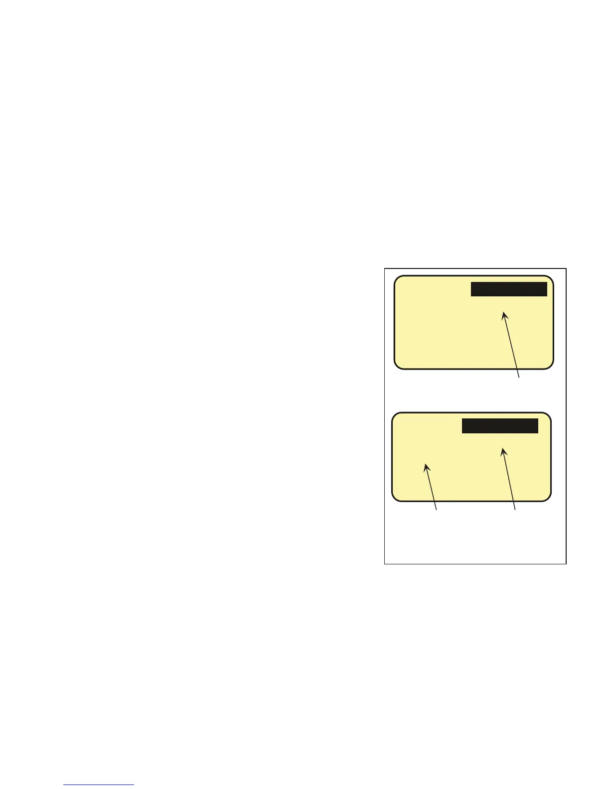
BTN 1
EDIT: LCP-1 ZONE-1
LCP1:
Z
1
Clock Screen when programming a panel in
the "8 or 16 Zone" Mode. "Load" is
replaced by "Zone" to indicate mode. Also
notice the small "z" in front of the number.